ALL-PUMPS — THE LEADING SOURCE OF INDUSTRIAL PUMPS AND FLUID HANDLING EQUIPMENT SINCE 1972
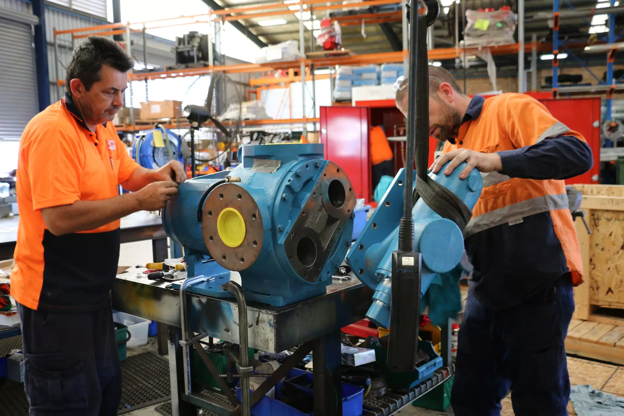
Our team is fully equipped and knowledgeable to provide professional and reliable industrial pump sales and services to customers across Australia. We design industry-specific pump solutions to help increase your efficiency and lower your costs.
Discover a wealth of knowledge, gain valuable insights, and stay up-to-date with the latest news about industrial pumps from All-Pumps, Australia's market-leading pump specialists, by exploring our informative blogs filled with enlightening case studies.
Our proud legacy has been forged by innovation and serving the needs of our clients first and foremost. Simply, we listen, learn and act. That’s why we’re the first preference for pump suppliers in Australia.
Roper gear pumps and Graco air operated pumps
I think you guys are very responsive. The staff know their products, good stocks, and supply quickly. No bad experiences. I think you are a pretty good organisation, and you are willing to help.
Jackson
Industrial adhesives manufacturing plant QLD
Graco pumps
Good service, prompt response on quotes from salespeople, quick response if there’s any questions, and that just makes everybody here happy.
Viraj
Brick manufacturing plant
Air operated diaphragm pump repairs and service
We never had any problems with All-Pumps generally speaking. Pretty good, all the engineers and sales guys we've talked to are helpful.
Geoff
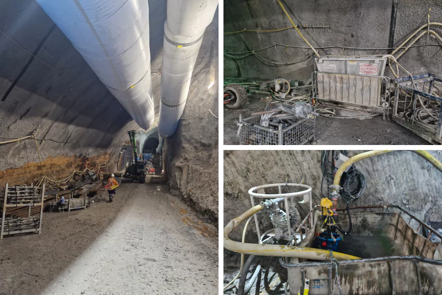
Coal mining customer
Tuthill gear pump
You always get what i want inside the timeframe so it's a pretty good job.
Robert
Oil and gas customer
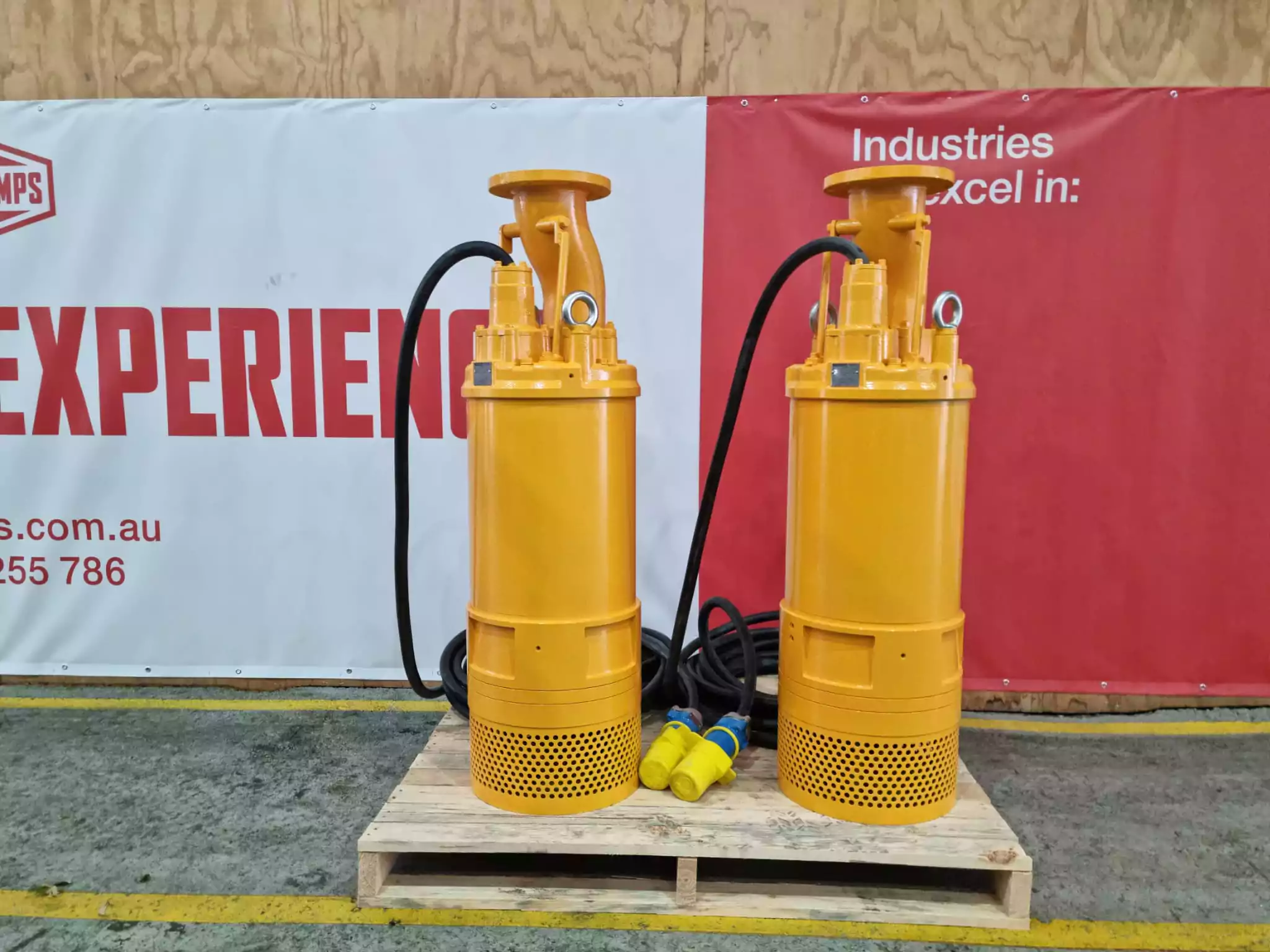
Grundfos ss submersible stormwater pump
...your service has been prompt. Pretty good. I ordered around 7-8 pumps in the last months and i have no issues.
Ayyash
Food and beverage manufacturing customer
Grundfos pump
Very happy with you people. No complaints. Quotes have been better from anyone else. I'm happy with this.
Paul
Fruit juice manufacturing customer
Subscribe to our Newsletter
Get the latest promos, new products, spare parts, data sheets, white papers, case studies, brochures, and catalogue updates delivered straight to your inbox!
All-Pumps offers a bespoke solution to your pump problems. Call our professionals if you need a new pump, replacement part, repair services, system design, or monthly maintenance!
Our customer support services are the best in the field with 100% customer satisfaction ratings.
Free quote for installation.
Free quote for servicing.
Free quote for custom system design.
Free quote for pump or spare pricing.
Pump guides
And so much more!!!
Get in Touch
Fill out the quick form below and one of our sales officer will get in touch with you in a lightning speed!