Discover Relevant Articles
Stay informed with our blog, featuring relevant articles on industry trends, best practices, and expert insights.
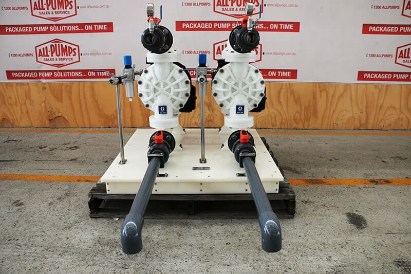
AODD pumps are also known as:
- Air-operated double diaphragm pumps
- Pneumatic diaphragm pumps
- AOD pumps
They are used for endless mining, industrial, manufacturing, and various general applications. Powered only by compressed air, they are used where electricity isn’t available, in flammable areas, or in areas where an explosion is a high risk.
An AOD pump is a type of reciprocating diaphragm pump which contains two diaphragms driven by compressed air. The air section with a shuttle valve applies air alternately to the two diaphragms, each diaphragm has a set of check/ball valves.
In this post, we will explore the operating principle of an AODD pump.
Stroke 1
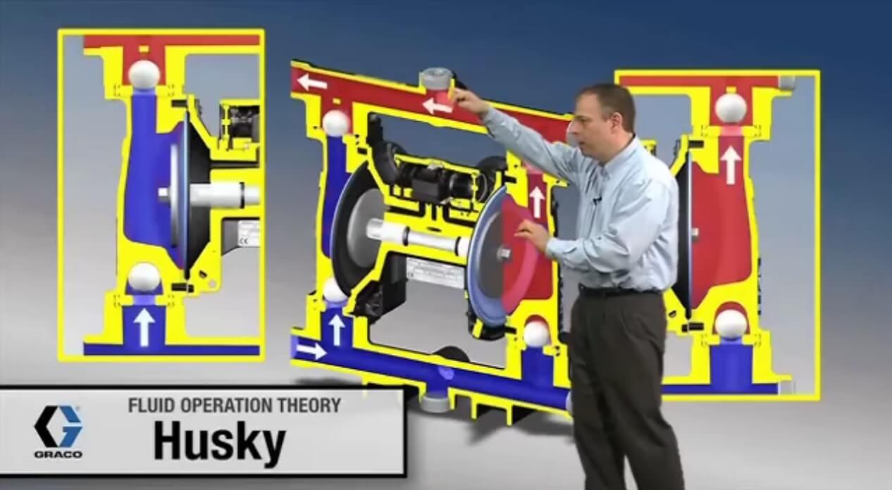
- The air valve directs pressurised air to the backside of Diaphragm A, pushing it away from the center of the pump. Acting as a separation membrane between the compressed air and liquid, the elastomeric diaphragm applies pressure to the liquid column, while also balancing the load in order to remove mechanical stress from the diaphragm
- As the compressed air moves Diaphragm A away from the center of the pump into its discharge stroke, the pressure created within Chamber A pushes out the liquid through its discharge valve.
- At the same time, the common shaft pulls the opposite diaphragm (Diaphragm B) inward on its suction stroke with the air behind it having been forced out to the atmosphere through the exhaust port of the pump.
- The movement of Diaphragm B toward the center of the pump creates a vacuum within Chamber B. Atmospheric pressure forces fluid into the inlet manifold forcing the inlet valve ball in Chamber B off its seat. The liquid is then free to move past the inlet valve ball and fill liquid Chamber B (see shaded area).
Stroke 2
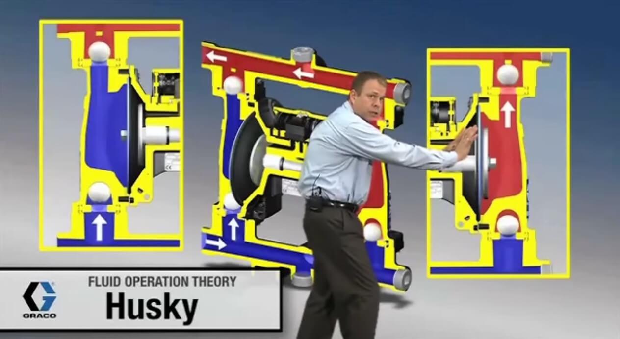
- When the pressurised diaphragm, Diaphragm A, reaches the limit of its discharge stroke, the air valve redirects pressurised air to the backside of Diaphragm B.
- The pressurised air forces Diaphragm B away from the center while pulling Diaphragm A toward the center via the common shaft.
- Diaphragm B is now on its discharge stroke, which forces the inlet valve ball in Chamber B onto its seat due to the hydraulic forces developed in Chamber B and the manifold of the pump. These same hydraulic forces lift the discharge valve ball off its seat in
Chamber B, while the opposite discharge valve ball in Chamber A is forced onto its seat, forcing fluid to flow through the pump discharge. - The movement of Diaphragm A toward the center of the pump creates a vacuum within Chamber A and the atmospheric pressure forces fluid into the inlet manifold of the pump.
- The inlet valve ball in Chamber A is forced off its seat, allowing the fluid being pumped to fill Chamber A from the inlet manifold.
1-Pump Cycle
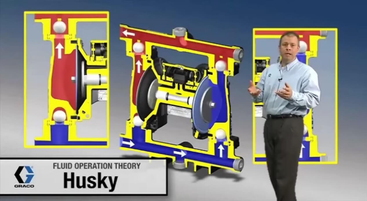
- At the completion of the stroke, the air valve again redirects air to the backside of Diaphragm A, which starts Diaphragm B on its exhaust stroke.
- As the pump reaches its original starting point, each diaphragm has gone through one exhaust and one discharge stroke. This constitutes one complete pumping cycle.
- The pump may take several cycles to completely prime depending on the conditions of the application.