You’ll enjoy the All-Pumps experience. We’re certain.

As one of the safest and easy-to-operate pumps, AOD pumps are used where electricity isn’t available, or in explosive or flammable areas.
AOD pumps are self-priming and have a vastly different pump performance curve than those of centrifugal pumps’.
Understanding the pump curve enable you to specify the AOD pump for optimum life and performance, thus reducing any unneeded downtime.
In this example, we’ll use Graco Husky 307 AOD pump with PTFE diaphragms.
On the vertical axis (Y axis), it indicates the discharge pressure, which is measured in psi (bar) or feet (metres). This axis also indicates the inlet air pressure.
On the horizontal axis (X axis), it specifies the fluid flow rate, which is measured in gallon per minute (gpm) or litre per minute (lpm).
The darker lines shown above indicate the air consumption, which is measured in standard cubic feet per minute (scfm) or metre cube per minute (m3/min).
Let’s imagine that we need to supply 3 gpm (11.4 lpm) of fluid flow at 50 psi (3.5 bar) or 115 feet (35 metres) discharge head pressure.
By travelling up the solid curve, it indicates that 70 psi (4.9 bar) or 160 feet (48.8 metres) of inlet air pressure is needed. The air consumption required is 3 scfm (0.084 m3/min).
Have questions about AOD pump curves? Let us know in the comment section below.
A pump’s performance curve is usually one of the first thing you should look at before purchasing a pump or when operating it.
But how do you read between all those weird lines? How do you know you got the right pump for the right job?
In short, a pump curve is a graphical representation of a pump’s performance based on testing conducted by the manufacturer.
Each pump will has its own pump performance curve and it varies from pump to pump.
This is based on the pump horsepower and the size and shape of the impeller.
Understanding any given pump’s performance curve enables you to understand the limitation of that pump.
Operating above its given range will not only damage the pump, it will also cause unneeded downtime.
A pump curve shows 2 vital performance factors – flow and head.
Flow is the rate that the liquid has to be moved throughout a system.
In SI units, it’s measured in litre per minute (lpm) or metre per hour (m3/h).
In English Engineering units (used in the United States), it’s measured in gallon per minute (gpm).
Different liquid has different viscosity, so be sure to understand their flow.
Let’s take a residential water heating system as an example.
Too much flow results in system noise, while too little flow means insufficient heat in some areas.
Pressure is measured in PSI, pound per square inch but in hydronic, pressure is calculated in term of head pressure or head loss as measured in head feet.
Head is the total mechanical energy content of a fluid at a given point in a piping system.

In order for the pump to move the fluid, it needs to product a sufficient pressure differential to overcome head loss in the system. Head loss are created in the piping by friction and by the various valves and fittings.
1 PSI system pressure drop equals 2.31 head feet.
In SI units, head is measured in metre (m).
In English Engineering units (used in the United States), it’s measured in feet (FT).
In short, pump curve show you how a pump perform at any given point of its range.
We’ll use Sabre Bav series pump curve as an example.
Below diagram demonstrate that at a flow rate of 100 lpm or 6 m3/h, the pump will produce 3.5 m of head.
In English Engineering units (used in the United States), at a flow rate of 26 gpm, the pump will produce 11 FT of head.

At a flow rate of 100 lpm or 6 m3/h, the pump will produce 3.5 m of head.
Below diagram demonstrate that at 2 m of head, the pump will have a flow rate of 138 lpm or 8.4 m3/h.
In English Engineering units (used in the United States), at 6.5 FT of head, the pump will have a flow rate of 38 gpm.

At 2 m of head, the pump will have a flow rate of 138 lpm or 8.4 m3/h.
If the head and flow operating point of your system is on or below a given pump curve, then that pump will be sufficient.
In the 2 scenarios given above, a BAV-150 will do the job.
As a rule of thumb, the best efficiency point (BEP) is about 85 percent of the shutoff head. It is important to note that the pump should be operated at, or close to, the best efficiency point.
BEP is usually specified in the manual or the pump curve itself. If not, you’ll have to contact the pump manufacturer.
Have questions about pump curves? Let us know in the comment section below.

A lot of food and personal care processing facilities hire staff to manually scoop out product from a drum. Some even clamp the drum, raise it and then dump the product directly into a kettle.
After this initial process, they will spray water to remove the residual material from the bottom and sides of the drum.
These processes are OH&S nightmares and can be hazardous due to potential employee injury and food safety.
Installing a drum unloading system can help prevent both of these issues within a processing facility.
It usually take over 30 minute to manually scoop or to clamp up a drum and dump it into the kettle and then spray out the residual with water.
A drum unloader takes about 5 minute.
In additional, the manual processes will introduce water to the material and the water needs to be removed at a later part. As a result, more time and money are needed to remove the contaminants from the product.
A high-performing drum unloader with an inflatable wiper seal will leave behind less than 1 percent residual product. This contributes to overall cost-saving.
Think about the potential of contamination when people are leaning over drums and manually scooping the product. Open drum also expose the product to airborne bacteria, something a drum unloading system can easily eliminate.
Having a drum unloader in place also reduce employee’s injury risk and improve plant personnel safety.
All Pumps customised and supplied a mobile Graco Saniforce drum unloading system with protection barriers and piping for a food processing plant in Australia.
The drum unloading system was able to be washed according to sanitary standards with the pump being FDA and 3A approved. Beside being a great solution for unloading multiple drums, it also reduce time, cost and employee’s injury risk.
Factory Acceptance Test and related documentation was also provided to the customer.
A Saniforce drum unloader is capable of unloading a regular tomato paste drum in 4 minute, with diluting the material.
It can unload medium to high viscosity products, up to 500,000 cps, from 55-gallon containers.


Saniforce by Graco has a wide range of drum pumps, diaphragm pumps & bin unloaders. They are efficient, low-maintenance and suitable for a wide array of applications.
All Pumps has been importing, servicing and supplying Saniforce pumps in Australia for many years and will be more than capable of answering any doubts or questions you have. Know more.

A centrifuge is a piece of equipment that spin an object in rotation around a fixed axis, in order to achieve sedimentation. Centrifuges are used in many industries, such as chemical and food, to separate unwanted particles and waste from the system.
Solids tend to make up a huge percentage of the waste produced, making waste transfer challenging.
An industrial client faced some problems trying to transfer their centrifuge waste. Their waste is made up of 50% solids and were transferred manually by staff near large moving machinery, thus posing a huge risk to the employees as well.
On top of that, the pump needs to fit under the centrifuge in a limited space and transfer the waste to bins 15 metres away.
All Pumps engineered a Netzsch progressive cavity pump with an inline ogre, to feed the slurry into the pump, and a right-angle mounted motor to ensure the pump would fit in the designated length.
The helical rotor pump was not only a very cost effective solution, it has proven very reliable with minimum maintenance and high performance.
The Netzsch pump was installed in a hazardous rated area and was rated to suit this classification.
Progressive cavity pumps can handle difficult, thick and solid laden liquids. They are used extensively in water treatment plants, sludge and chemicals.


In power generation industry, water from boilers are circulated to various parts of the plant.
Overflow tanks are used in such industries to avoid hot water spillage, which otherwise can be potentially hazardous.
Based on the customer's requirements, we designed and supplied a 1350 litres blowdown overflow tank with an Ebara 316SS centrifugal pump, coupled with E3 IP66 motor to pump water at 100 degree C.
The blowdown system, including the tank base and pump skid, was constructed in full 316 stainless steel.
Pump operation was controlled by a liquid level pressure transducer at the bottom of the tank in conjunction with an advanced single pump controller.
The pump was programmed to start and stop automatically upon water reaching a predetermined high and low level. These levels can be modified using the HMI screen, located within the advanced pump controller.
All items were supplied to the project’s required temperature rating of 100 Degrees C.


All Pumps recently supplied 2 containerised fire pumps to a fuel terminal. These diesel driven units are built to AS2941 standard and having them within shipping containers offer several significant benefits.
First, the sea containers help protect the fire hydrant systems from the harsh condition and elements, thus increasing the operational reliability should there be an emergency.
The container also reduces the amount of cleaning and maintenance required to keep the radiators and cooling fans working efficiently.
In the event of a fire, the container will slow down the fire’s progress significantly and protect the fire hydrant systems for a period of time.
Having a fully tested, pre-commissioned containerised fire pump also means shorter installation time and minimal on site assembly.
In addition, by enclosing the fire pumps within the shipping container, noise levels are greatly reduced.
All Pumps provides turnkey pump solutions to suit your project. We’re ISO certified and is a supplier member of Achilles FPS Oil & Gas Asia Pacific.


Hydrocarbons are important in modern society as fuel, solvents and even as the building block of plastic.
They originated from crude oil and since crude oil consists of other organic compounds as well, they cannot be used effectively by modern industries.
Thus petroleum refining processes transform crude oil into useful products such as LPG, petrol, kerosene, jet fuel, diesel, and fuel oils.
Similar to many industrial processes, this refining process produces by-products and undesired waste.
Our client needs to transfer hydrocarbon wastewater from a pit to the treatment plant, which is located on the other side of the plant.
After treatment, the water will be reused for other purposes on site.
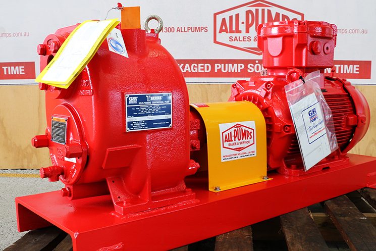
Using a Gorman-Rupp self-priming centrifugal T series pump, we are able to achieve the priming, high flow and medium head requirements with a very reliable solution.
Before varies petrochemicals, the self-priming pump will also pump the occasion solids.
It stands up well with a channel vane impeller and viton elastomers.
Gorman-Rupp centrifugal pumps are widely used in the municipal, wastewater, sewage, industrial, construction, petroleum and OEM markets.


For more than 80 years, Gorman-Rupp has manufactured high quality pumps and pumping systems required for lasting service in the municipal, wastewater, sewage, industrial, construction, petroleum and OEM markets.
Know more
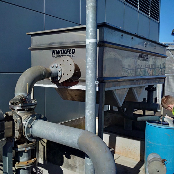
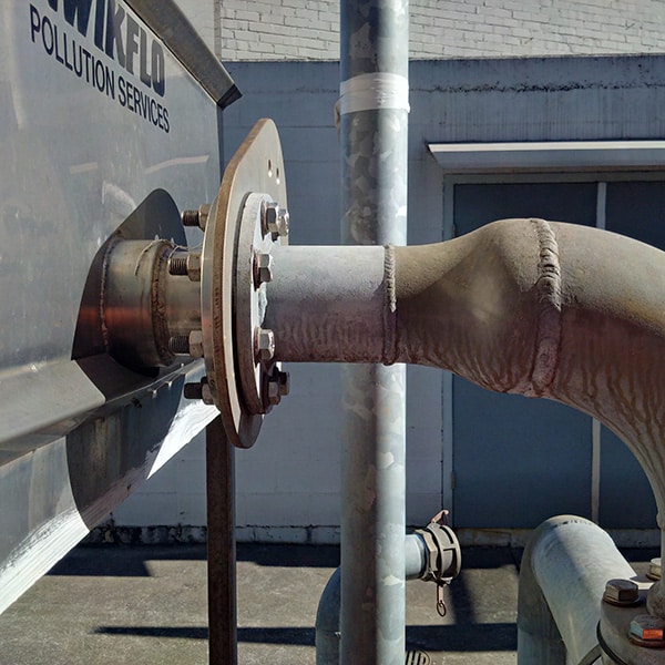
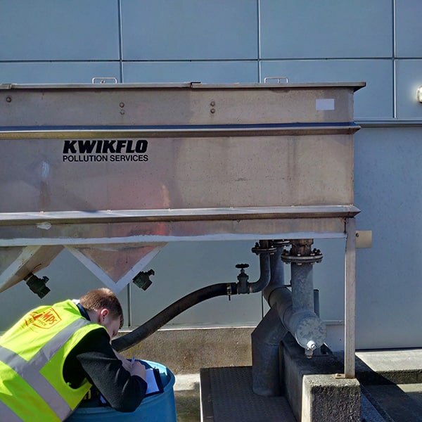
A site in Sydney requires an upgrade to their current Kwikflo stainless steel oil water separator which was previously supplied by us.
There is nothing wrong with the old oil-water separator and it’s part of a routine upgrade to ensure there is no downtime in the future.
Due to the site’s location and application, the stainless steel oil-water separator we supplied years ago is a special build.
Our service manager, Andrew Dent, and draftsman, Jacob Begg went down to the site to inspect the site and jot down the measurements.
Based on the drawing produced by Jacob, we manufactured and supplied a upgraded Kwikflo KCPS-15000 stainless steel oil water separator.
It is corrosion resistance and is able stay operational for a number of years.
The plumber, who installed it, commented that it fitted exactly to all the pipework connections without the slightest alteration!
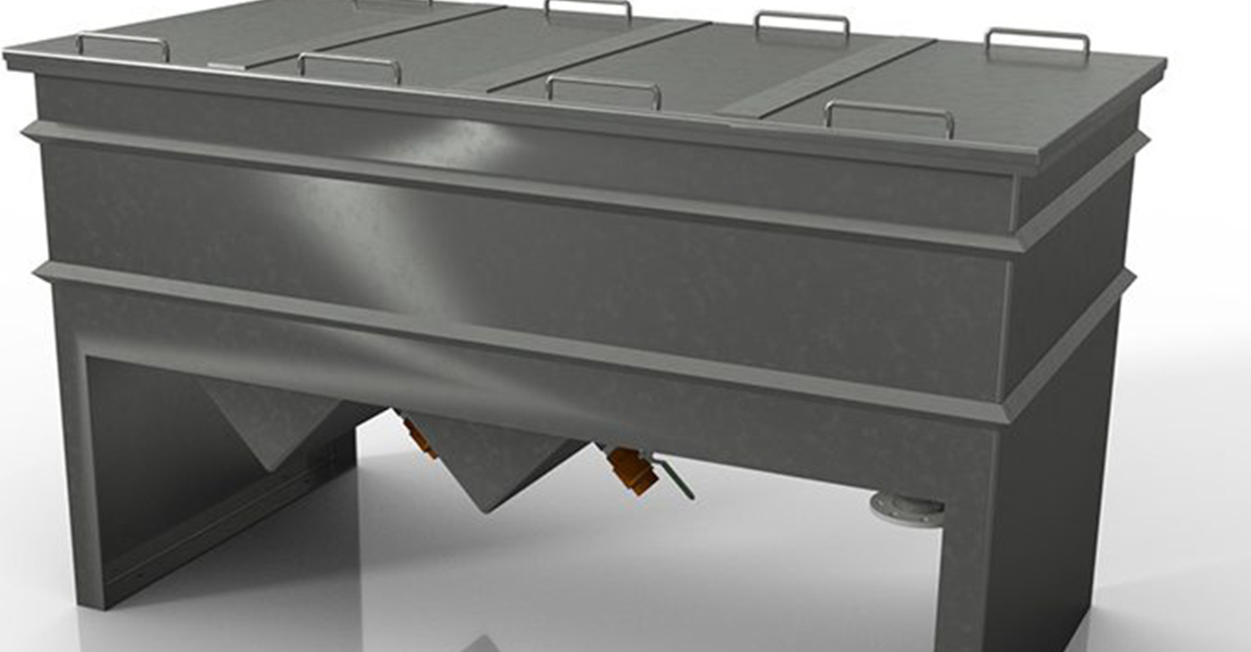
Oil water separators are enhanced gravity systems required to remove oils and solids from water. Commonly used in vehicle wash stations and mechanical workshops, oily water is pumped through to an inlet chamber where solids settle out and oil immediately rises to the surface.
After the oily water is separated, an oil baffle prevents it from entering the outlet weir. The waste water is then discharged to sewer, the solids to the in-built hopper and waste oil to a drum underneath.
All Pumps manufactures and supplies the Kwikflo range of pumps, pumping equipment and systems, including associated accessories and options for a variety of industry groups including Building Services, Civil and Construction, Mining, Fire Protection, Environmental and Rainwater Harvesting.
All-Pumps has these pumps and parts in stock and is ready to help with your requirements today.

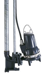
Submersible pumps are highly versatile and come in different sizes. They are employed in many applications and one such is water diversion projects, where it works flawlessly.
Modern day golf courses are constructed with excessive landscaping in which water is continuously recirculated as small creeks within. However, in the event of a storm, these creeks have the potential to flood areas within the golf course which otherwise need to be maintained dry and hence can damage the landscaping.

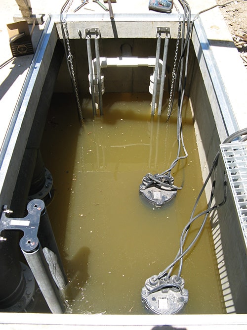
SYDNEY GOLF COURSE
All Pumps was awarded with a design, supply and construct contract for a pump station that could recirculate water within a golf course in Sydney and divert excess water to a holding dam in the event of storms.
Two of the smaller SEG pumps were installed in a duty-standby configuration to recirculate the water within the golf course, while the other two larger SEG pumps were installed in a duty-duty assist configuration to dewater excess water from the golf course in the event of a storm to avoid flooding.
In addition to installation of the concrete pump station, the project also involved pump associated electrical works, excavation and installation of pipework between the stormwater pumps and a holding dam.
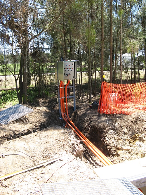
Besides functionality, the concrete pump station also fits in nicely with surrounding environment.