
You’ll enjoy the All-Pumps experience. We’re certain.
10 November 2017 – We opened the doors to the public at our headquarters in Silverwater, NSW.
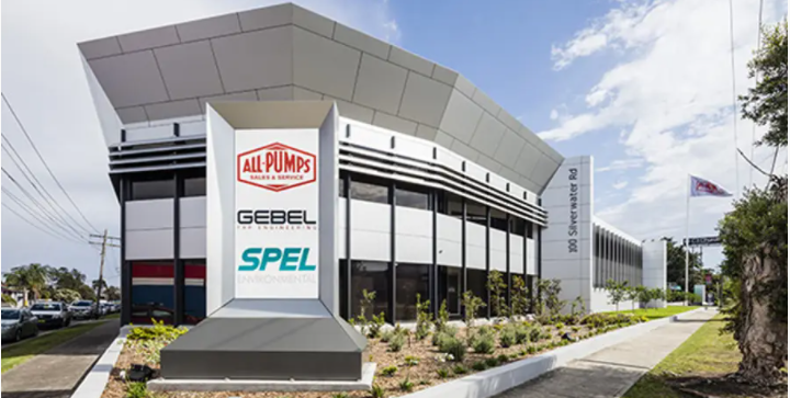
ALL PUMPS SILVERWATER OFFICE
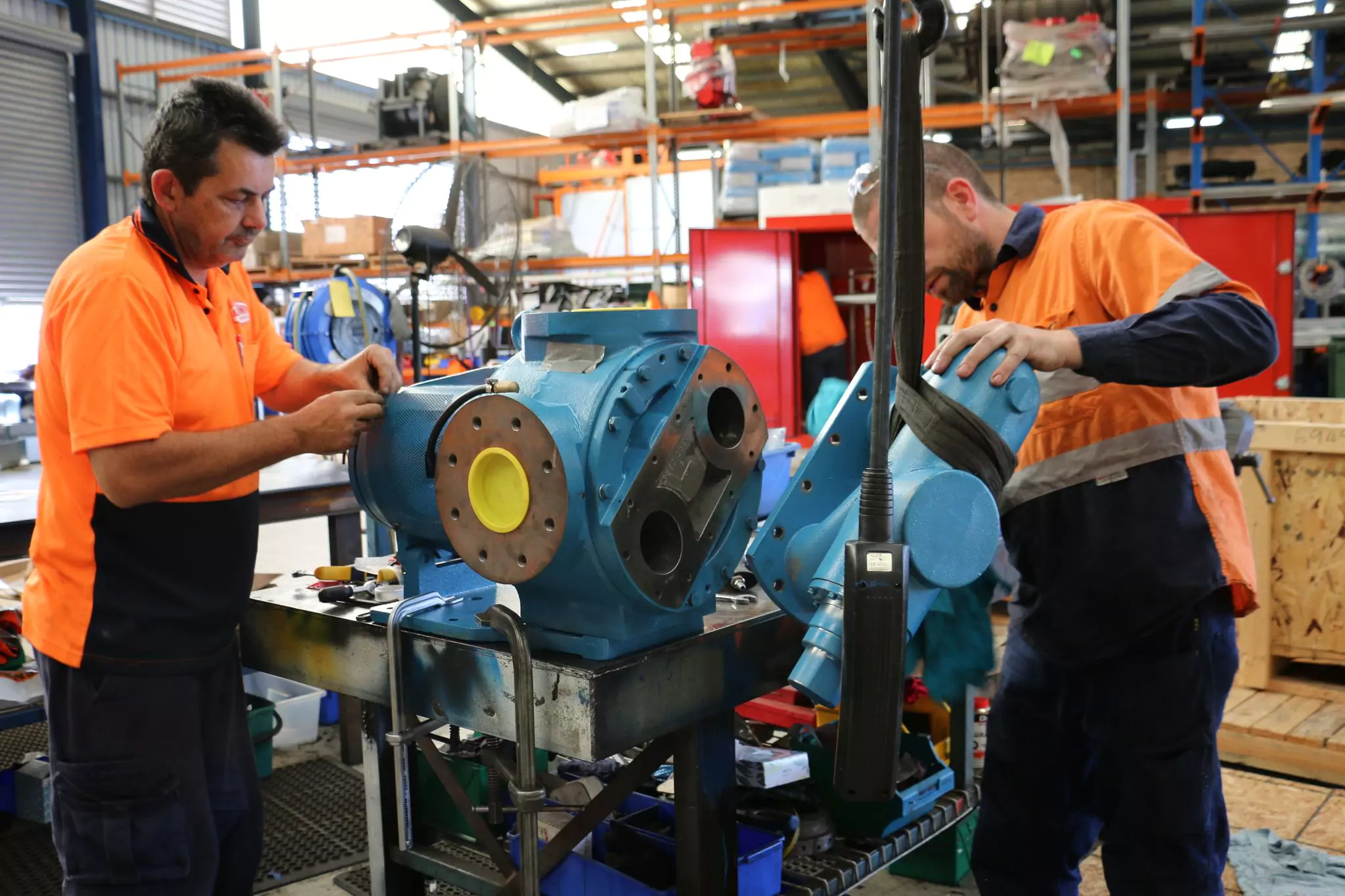
Throughout the day, visitors were offered a unique opportunity to check out our facility, see our extensive range of products for different industries as well as have access to our professional team to answer any questions they might have.
Visitors were greeted by our team and given a tour of the facility where products were put on display.
Products put on display such as the SPEL filter, fire booster system, pressure bosster systems, SPEL stormceptors, among many others.
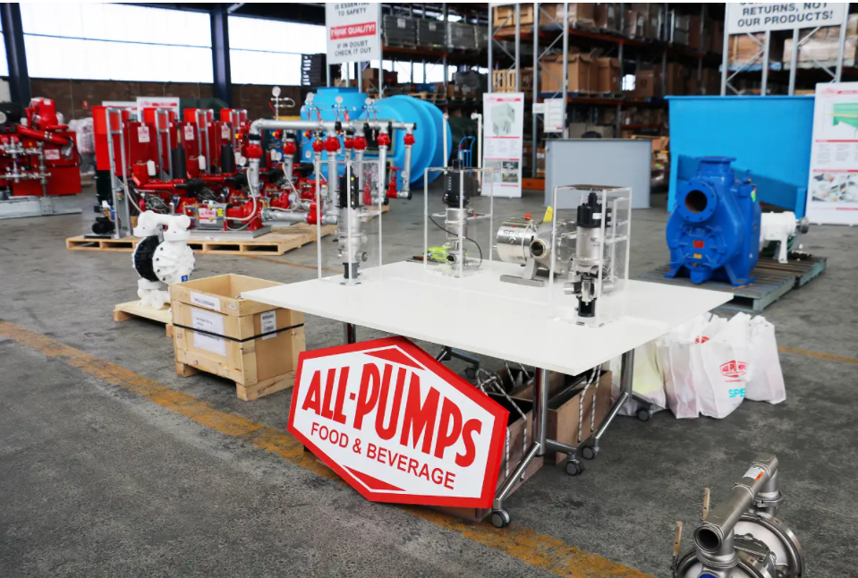
PUMPS FOR THE FOOD AND BEVERAGE INDUSTRY
Another highlight of the day was the presence of a virtual reality headset that everyone could try. It allowed to do virtual tour of projects site and closely examined 3D models of pumps and their inner parts. This represents an interesting window in what might become an integral part of pumps servicing in the near future through further development of technologies such as virtual reality and augmented reality.

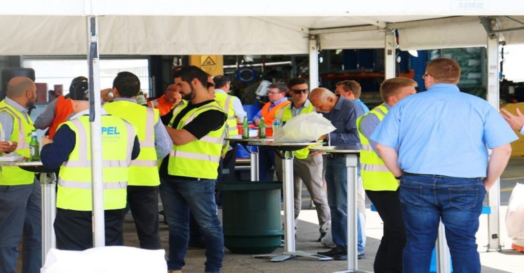
The day represented a nice opportunity to network with other industry specialists in a friendly environment over some food and drinks that were organised for the day.
We thank our visitors for taking time off their busy schedules to give us a visit and making the day a success.
It was a great opportunity to develop our business relationships to ensure we can cater to our customers exact need. We would really welcome any feedback on the open day to help us tailor it further to your expectations. So please, do not hesitate to contact us.
Be sure to stay tuned for news about the next Open Day.
With over 40 years of experience, All Pumps Sales & Service has been dedicated to providing solutions in all fields of fluid handling. We have been customising pumps to the exact requirements of clients in the civil and building industries with a range of robust, reliable pumps and environmentally approved pollution control systems.All Pumps is happy to take any inquiries, and is ready to help with your requirements today! Contact Us
Find out for yourself by watching the video below:


With over 40 years of experience, All Pumps Sales & Service has been dedicated to providing solutions in all fields of fluid handling. We have been customising pumps to the exact requirements of clients in the civil and building industries with a range of robust, reliable pumps and environmentally approved pollution control systems.All Pumps is happy to take any inquiries, and is ready to help with your requirements today! Contact Us

Manufacturers of food and beverages, pharmaceuticals or cosmetics use components and make products that are among the most expensive in the world.
Significant and immediate cost savings can be achieved by improving the volume of premium end-products and costly materials that are recovered from transfer lines. Given the value at hand, any potential for increased retention and recovery is worthy of exploration.
Product waste is always the enemy of profitability, and even more so when the products have a high cost. More than $120 billion of product goes to waste worldwide every year, according to the McKinsey Quarterly Food Waste Alliance. The Natural Resources Defense Council (NRDC) has also studied the issue and found that 40 per cent of food in the United States is lost during handling and production.
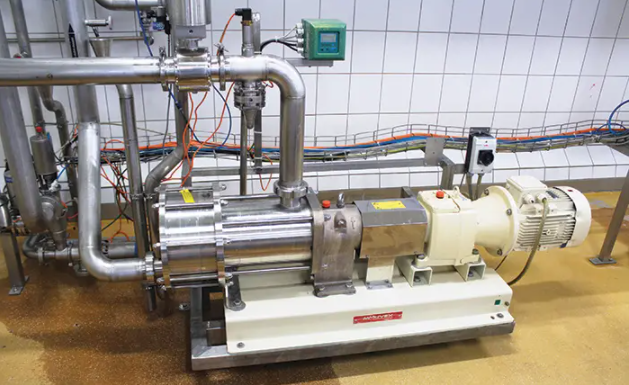
HYGIENIC MANUFACTURING OPERATIONS IN THE FOOD AND BEVERAGE, PHARMACEUTICAL AND COSMETIC INDUSTRIES OFFER MANY AREAS WHERE PRODUCT RECOVERY CAN BE OPTIMIZED WITH THE USE OF ECCENTRIC DISC PUMP TECHNOLOGY. (COURTESY OF PSG)
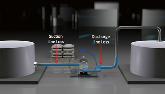
In hygienic manufacturing, some waste is inevitable, but there is a direct path to significant product recovery. By recovering raw ingredients or intermediate/finished products that remain in the suction or discharge fluid-transfer lines after production runs or between changeovers, a company can eliminate a substantial amount of waste. When transfer pumps lack the capability to adequately clear production lines, there is a snowball effect on costs. Some companies flush the lines and accept product losses, but there are often ancillary costs, including:
Some plants use product recovery hardware, but a so-called “pigging” system, or other line-clearing solution, comes at a considerable cost premium and adds unnecessary complexity to the pumping operation. The pigging system might provide excellent product-recovery rates, but it also must be purchased, installed, operated, maintained and eventually replaced.
There is a better option. With the right transfer pump installed, manufacturers can recover the bulk of their product from the line and achieve considerable savings with every production cycle. This capability to clear lines varies among pump types. The lobe, external circumferential piston (ECP), twin screw, centrifugal, hose and progressive cavity-style pumps widely used in hygienic manufacturing lack the capability to adequately strip suction or discharge lines.
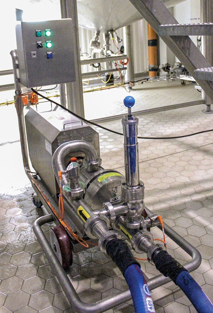
ECCENTRIC DISC PUMPS CAN BE USED IN HYGIENIC MANUFACTURING IN TWO WAYS, FIRST AS A NORMAL PROCESS PUMP, THEN AS A WAY TO INCREASE PRODUCT RECOVERY. THE RESULT IS LESS WASTE OF CRITICAL RAW MATERIALS AND EXPENSIVE FINISHED PRODUCTS, RESULTING IN A HEALTHIER BOTTOM LINE.
An eccentric disc pump, on the other hand, can clear a minimum of 70 per cent of product from lines on its own power—without the aid of any additional component systems that would increase capital expenditure, system complexity and maintenance requirements.
The cost-saving potential is enormous. One manufacturer of eccentric disc pumps for hygienic manufacturing estimates that some companies can realise annual savings in the hundreds of thousands of dollars or greater if eccentric disc pump technology is incorporated into a hygienic manufacturing system.
As the example suggests, the potential savings are entirely dependent on the application. The following are examples where the use of eccentric disc pumps has resulted in documented six-figure savings per pumped line:
Strong product recovery is possible with eccentric disc pumps because of their unique design. Each pump employs a disc that moves on an eccentric plane within a circular channel, creating the capability for non-pulsing, low-slip operation with high volumetric consistency. The operation of eccentric disc pumps allows flow rates to vary minimally despite changes in viscosity, temperature, system back pressure and even component wear.
ECCENTRIC DISC PUMPS ARE SO EFFICIENT AND VERSATILE THAT THEY ARE ABLE TO PUMP AIR EVEN WHEN NO FLUID IS PRESENT, WHICH ENABLES THEM TO COMPLETELY AND SAFELY CLEAR BOTH SUCTION AND DISCHARGE LINES DURING HYGIENIC-PUMPING PROCESSES.
Eccentric disc pumps can operate with such high efficiency that they can pump air when no fluid is present, which creates a vacuum effect on the suction side and a compressor effect on the discharge side of the pump. Once the product runs out in the feed tank, the eccentric disc technology continues to pump air in a very constant, non-abrupt, non-pulsating manner, so that the surface tension on any remaining fluid is not broken. This produces a plug effect, which pushes out the product “plug” as a whole.
Because eccentric disc pumps transition to the purging process by using the air that is already in the feed tank, product purity is rarely an issue. In certain applications, the operator purifies the air or gas blanketing the product to protect purity. This method of product recovery is much safer and cleaner than pigging or a basic air/gas-blowing process. It also eliminates the risks and costs associated with sourcing air or gas compressors or high-pressure bottles.
The typical amount of product recovered with an eccentric disc pump is more than 95 per cent on the suction side of the pump and typically 60 to 80 per cent or more on the discharge side. There are additional benefits of using eccentric disc pumps in product-recovery applications, including:
Compared to eccentric disc pumps, twin screw, lobe and ECP pumps lack line-cleaning capabilities, and manufacturers often have to use them in conjunction with pigging systems that use a projectile to push out the residual product. While well-installed pigging systems deliver the highest recovery rates, they can only be used in lines that are built without the interruptions of ancillary components, such as heat exchangers, valves, filters and flow meters. Operators must also take great care to ensure that purified compressed gas or air is used to push the pig, which can prove a challenge for maintaining product purity.
Twin screw, lobe and ECP pumps also wear constantly, which increases their internal clearances over time, resulting in product slip that reduces flow capacity and volumetric efficiency as operating pressures and fluid viscosities change.
These pump types are also designed with two shafts that have to be sealed, which doubles the number of areas where leaks can occur. Twin screw, lobe and ECP pumps are also not dry self-priming and can run dry for only a short period of time unless they have flushed double-mechanical seals. These pumps will also experience diminished performance when handling low-viscosity materials.
The use of eccentric disc pumps as a cost-saving measure is a breath of fresh air for managers and engineers at hygienic plants, who may have run into a cost-reduction wall. Many operators have pursued pump efficiency for cost savings, but there is very little room to improve motor efficiency with today’s designs.
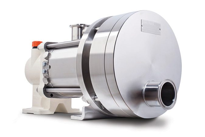
ECCENTRIC DISC PUMPS
Installing a higher efficiency positive displacement pump might yield electricity cost savings of only $200.
Savings of $32,000 a year on product recovery, as suggested in the example system, does a lot more to move the needle. In the model cost scenarios discussed here—$200 for the pump energy savings and $32,000 for the product recovery savings—the savings is 160 times higher with product recovery. Put another way, the product-recovery savings accumulated in one year with this example will pay for 32 years of energy to operate the pump.
Lobe, ECP and twin screw pumps are popular, but their lack of line-clearing capabilities means optimized product recovery will never be realized.

Tuthill’s manufacturing expertise and knowledge of applications enable them to provide you with an engineered solution. With All-Pumps we are also ensuring your satisfaction with post-sales service. We pride ourselves on properly servicing you with specification, installation, operation, and troubleshooting.
The pump was originally designed to meet and exceed the exacting requirements of the refrigeration compressor market. The design has so many inherent features and benefits that our traditional customers are also seeing the advantages. The excellent performance of the 1000 series pumps are solving problems in many industries and varying applications.
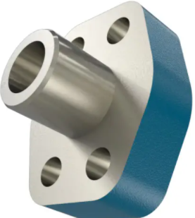
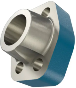
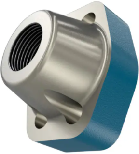
1000 Series pumps are based on the proven internal gear principle, and have been enhanced in response to demands from our OEM customers for a pump that offers advanced features which make installation easier. These side-ported pumps have the option to bolt SAE/DIN flanges onto them ensuring maximum flexibility on the porting arrangements. Tuthill’s goal was to design a pump that meets your technical requirements and is easily fitted into your system. The 1000 Series pumps are mechanical seal fitted and have a Carbon Bushing Idler as standard. Options are available for lip seals on direct-mounted pumps and a choice of ball bearing or carbon bearings in the body.
The 1000 Series pumps are fitted with SAE/DIN flanged ports, which enable Tuthill to offer various port options. Tuthill has the ability to build your pump with threaded, butt weld, socket weld ports, or a blank flange. The blank flange can be tapped to your specific requirement.
The 1000 series is designed to be close coupled directly to IEC or NEMA motors. This compact mounting process enables a smaller footprint, but also automatic shaft alignment when changing pump heads.
Vertical mounting optimizes the fit of the pump into smaller footprints. This is a highly requested configuration whenever floor space is limited. It is recommended that if the pumps are to be mounted in this manner, it is indicated at the inquiry stage of the buying process.
All the adapters can be supplied with a tapped port to facilitate fitting of a clear bottle. The bottle is used as a sight glass to determine seal status.
The 1000 series symmetrical design provides added flexibility. The pump head can be rotated in 90° increments, creating the ability to change port alignment from horizontal to vertical or reversing suction and discharge ports.
| Flow Rate at 50HZISO 32 at 104 °F (40 °C) 50 PSI (3.45 BAR) | Flow Rate at 60HZISO 32 at 104 °F (40 °C) 50 PSI (3.45 BAR) | |||||||||||
|---|---|---|---|---|---|---|---|---|---|---|---|---|
| 720 RPM | 960 RPM | 1425 RPM | 860 RPM | 1150 RPM | 1750 RPM | |||||||
| MODEL | GPM | LPM | GPM | LPM | GPM | LPM | GPM | LPM | GPM | LPM | GPM | LPM |
| 1010 | 2.31 | 8.73 | 3.12 | 11.82 | 4.71 | 17.82 | 2.76 | 10.45 | 3.74 | 14.16 | 5.64 | 21.35 |
| 1012 | 3.84 | 14.55 | 5.04 | 19.09 | 7.21 | 27.28 | 4.61 | 17.45 | 6.05 | 22.90 | 8.64 | 32.71 |
| 1014 | 6.25 | 23.64 | 8.29 | 31.37 | 12.43 | 47.05 | 7.49 | 28.35 | 9.94 | 37.63 | 14.90 | 56.40 |
| 1015 | 7.00 | 26.50 | 9.31 | 35.23 | 13.85 | 52.42 | 8.40 | 31.80 | 11.16 | 42.25 | 16.61 | 62.88 |
| 1017 | 14.39 | 54.46 | 19.25 | 72.87 | 28.52 | 107.97 | 17.26 | 65.34 | 23.09 | 87.41 | 34.20 | 129.50 |
| 1020 | 22.42 | 84.87 | 31.02 | 117.42 | 47.53 | 179.93 | 26.88 | 101.75 | 37.20 | 140.82 | 57.00 | 215.77 |
| 1022 | 30.83 | 116.70 | 43.54 | 164.80 | 67.05 | 253.80 | 39.96 | 151.27 | 52.20 | 197.60 | 80.40 | 304.35 |
| 1024 | 79.26 | 300.04 | 106.58 | 403.46 | *147.60 | *558.71 | 95.04 | 359.77 | 127.80 | 483.78 | *190.2 | *719.99 |
*4″ Ports
Tuthill Pump Group has been providing positive displacement lubrication pumps for demanding OEM applications since 1927. Since that time, our product portfolio has developed to expand into a variety of markets and applications. Tuthill Pump products successfully handle applications from an extremely low-flow capacity with a high level of accuracy, to applications that are nearly solid in consistency with abrasive characteristics. Contact Us

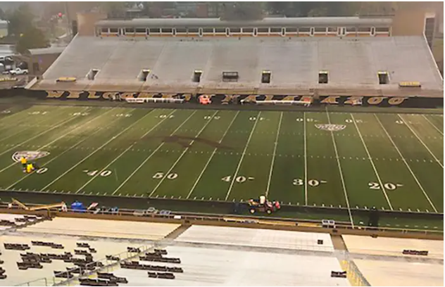
TORRENTIAL RAIN LEFT 2 MILLION GALLONS OF WATER ON THE FIELD, DELAYING A GAME
Heavy rainfall and flooding delayed Western Michigan University’s homecoming game against Akron, but an all-night effort to pump nearly 2 million gallons out of Waldo Stadium kept the game on track.
The game was scheduled for Saturday, Oct. 14, but torrential rain pounded the city of Kalamazoo, Michigan that afternoon. The 78-year-old stadium is in a flood plain and has three pumps that eject water to a 60-inch concrete pipe that Arcadia Creek flows through.
There were several catch basin inlets by the stadium that also drained to the 60-inch stormwater line. The line was at capacity, so stormwater moved backward and pushed water back around the stadium, contributing to the field flooding.

WESTERN MICHIGAN UNIVERSITY’S WALDO STADIUM IS FLOODED, DELAYING A COLLEGE FOOTBALL GAME BY A DAY (IMAGES COURTESY WMU)
The creek was flooded. Eventually, water backed up and there were two feet of standing water on the turf.
After the adjacent baseball field couldn’t hold any more water, the first floor of the connecting Bill Brown Alumni Football Center began to flood. At that point, Peter Strazdas, WMU’s associate vice president for facilities management, made the decision to turn off the three pumps to keep the building from flooding more.
As Saturday went on, the rain finally stopped. The plan was to play the next day at 1:05 p.m., but a contingency plan was set to play at the field of Kalamazoo College, the nearby Division III school whose stadium sat on higher ground.
The all-night effort from WMU’s facilities team and Clean Earth Environmental Contracting Services kept WMU from having to give up a true home game.
“It was all about the will of the people,” Strazdas said. “My facilities team said, ‘We don’t play home games on someone else’s turf. We play on our turf.’”
But WMU needed help. Clean Earth provided four vector trucks and two large tanker trucks to transport the water elsewhere on campus. The effort was halted at 2:30 a.m. when another deluge put 12 inches of water on the field. That passed and, at 5:30 a.m., the entire turf was visible.
WESTERN MICHIGAN UNIVERSITY’S WALDO STADIUM IS CLEARED AND WMU IS ABLE TO PLAY FOOTBALL.
There were five rips on the turf that were seamed and rubber palates on the turf that were repositioned, but the field was deemed safe at 8 a.m.
“By 10 a.m., we had that baby looking good,” Strazdas said.
Six hours later, WMU fell 14-13 to Akron, but Broncos coach Tim Lester gave the overnight workers plenty of credit for getting the stadium game-ready.
Strazdas said that out of every crisis comes an opportunity, and WMU is consulting with engineers on how to pump water elsewhere. There will also be more people and equipment on standby when more heavy rainfall is in the forecast.
Still, it was a victory for the school even if it didn’t show up on the scoreboard.
“We’re still pinching ourselves wondering how the hell we did this,” Strazdas said.
The client was in need of a fire booster pump system to serve a large fuel terminal. The project responsibilities included design, manufacturing, assembly, testing and delivery of three (3) fire pump systems to meet the required duty of 380 Liters per second at 105.0m head.
Our fire pumps are customized to fit the customer’s needs, whatever they may be. All-Pumps offered a turnkey solution from design selection, manufacturing, assembly and testing of three (3) fire pumps to meet the requirement.
Horizontal Split Case centrifugal pumps were selected to meet the required duty point and were coupled to 750kW V12 twin-turbo diesel engines. Other ancillary items such as drive shafts, fuel tanks, fuel hoses, and engine control panels were designed and costumed built for the project whilst compiling to AS2941-2013 requirements.
Despite their size, these fire pumps were designed, built and delivered to the site in the required time duration with zero safety incidents during manufacturing and delivery.
Fire hydrant pump systems (also known as fire pumps, hydrant boosters, or fire water pumps) are high-pressure water pumps designed to increase the fire fighting capacity of a building by boosting the pressure in the hydrant service when mains are not enough, or when tank fed. Know more.

Q: What are throttling valves and how are they used to control flow rates?
A: Throttling valves are a type of valve that can be used to start, stop and regulate the flow of fluid through a rotodynamic pump. When the flow of a pump is regulated using a throttling valve, the system curve is changed. The operating point moves to the left on the pump curve when the flow is decreased.
Throttling valves are one way of controlling flow rates, by throttling flow directly or in a bypass line. Variable speed operation is an alternative method of controlling the flow of a system.
With the throttling valve control method, the pump runs continuously, and a valve in the pump discharge line is opened or closed to adjust the flow to the required value. To understand how the throttling controls flow rate, see Figure 4.11. With the valve fully open, the pump operates at Flow 2. When the valve is in the partially open position, it introduces an additional friction loss in the system, resulting in a new system curve that intersects the pump curve at Flow 1, which is the new operating point.

The head difference between the two curves’ operating points shown is the head (pressure) drop across the throttling valve.
It is usual practice with throttling control to have the valve partially shut even at maximum system design flow to achieve controllability. Therefore, energy is wasted overcoming the resistance through the valve at all flow conditions.
Radial flow (centrifugal pumps) have a reduction in pump power as flow rate is decreased, however, the flow multiplied by the head drop across the valve is wasted energy that could be recovered if speed control was used as an alternative. On the other hand, using throttling control with mixed or axial flow pumps, where the pump power curve is normally increasing with deceased flow, could lead to unacceptable increases in power consumption, which results in overloading the driver in addition to wasted energy.
When evaluating the life cycle cost, in addition to energy costs, maintenance cost of control valves need to be considered, particularly in oversized situations where excessive throttling is ongoing and results in cavitation across the valve. The result is that the life cycle costs of this widely used control method can be surprisingly high.
Q: We have experienced corrosion issues with our pumps. Are there different types of corrosion I should evaluate, and how does the corrosive nature of a process fluid impact pump selection?
A: Corrosion is the destructive attack of a material by chemical or electrochemical reaction with its environment. Chemical and electrochemical corrosion can be further divided into several subtypes of corrosion, which all pump users should be aware of in order to select proper construction materials and ensure the longevity of pump components. The following list provides general information about the different types of corrosion.

PREVENTING PUMP RESONANCE BEGINS PRIOR TO PURCHASE
Resonance can be a serious problem for new or modified pump installations. Pump resonance issues are best avoided before purchase with appropriate engineering, modeling, contract/purchase order language, oversight and commissioning to minimize the risk of accepting a costly and unreliable machine. New or modified pumps and drivers can result in operating frequencies that excite natural frequencies of the system, causing unacceptable high vibration that can delay commissioning, exceed allowable operating limits, shorten life and decrease reliability.
Machine natural frequencies are frequencies at which the machine tends to vibrate when excited by a cyclic force at or near the one of the natural frequencies. When this happens, the energy from the input force is not dissipated but rather amplified, creating a resonant condition. In other words, a small pump vibration amplitude at a natural frequency can be amplified to a severe and unacceptable amplitude. Effective mass and stiffness of the system determine the natural frequency, both of which can be difficult and costly to change after installation. Here, system is defined as the driver, pump, bearings, attached piping, base and foundation.
All pumps are susceptible to resonance, but special attention should be given to variable speed pumps. As expected, variable speed pumps have a much greater chance of exciting natural frequencies since excitation frequencies vary with pump speed according to the process demand. So instead of avoiding a few discrete fixed frequencies, multiple and overlapping bands of frequencies must be considered. This is where modeling can come in handy. It allows users to evaluate multiple design scenarios, dampening options and speed ranges. The upgrade of a pump from a fixed speed drive to a variable speed drive can easily place the pump in a resonance condition that did not previously exist.

The first step is to ensure that natural frequency is addressed in the contract or purchase order for power generation and other process applications. The sample natural frequency contract language below might be too specific, or too vague, depending on the system provider, purchase value, criticality, size and complexity. Certainly other technical aspects of contracts like vibration limits, performance, etc., would be included.
The provider will guarantee that no operating frequencies of the installed driver/pump system will be within plus or minus (±) twenty percent (20%) of any natural frequencies of the driver/pump system. Operating frequencies are defined as, but not limited to, shaft speeds, vane pass, gear mesh, electrical, etc. System is defined as, but not limited to, the driver, pump, bearings, coupling, attached piping, supports, base, foundation, attached ladders/platforms, instrumentation and power conduit. The provider will make available design, engineering, modeling data, calculations and explanations at specified procurement hold points for review by the purchaser or the purchaser’s designated third party. Natural frequencies will be identified and measured after installation by an independent contractor using acceptable modal analysis testing. If natural frequencies are found within ± 20% of operating frequencies the provider will begin a root cause analysis immediately, and present a correction plan within xx days, and an engineered solution within xx days.
Even with appropriate language and technical due diligence carried out, unexpected resonance can still happen. All parties involved should be incentivized to enthusiastically find a solution.
So who are the responsible parties involved? In large plant construction projects with many systems being installed, the engineering, procurement and construction (EPC) company should be held responsible with contract language. However, their focus on potential resonance problems will not likely be a high priority in the grand scheme of the project. EPCs normally pass down the requirements in their vendor purchase specifications. For new singular system installations, the provider should be held responsible for the system being installed. When more than one provider is involved—for example in cases where the driver/pump is from one provider but the foundation is from another—make sure both are held responsible and the two are contractually required to exchange data/information. This might be a good case for the purchaser to hire a third party consultant. Another common scenario is replacing an existing driver or pump with a different design, which can cause a problem if the provider is not required to evaluate the existing system and foundation/support.
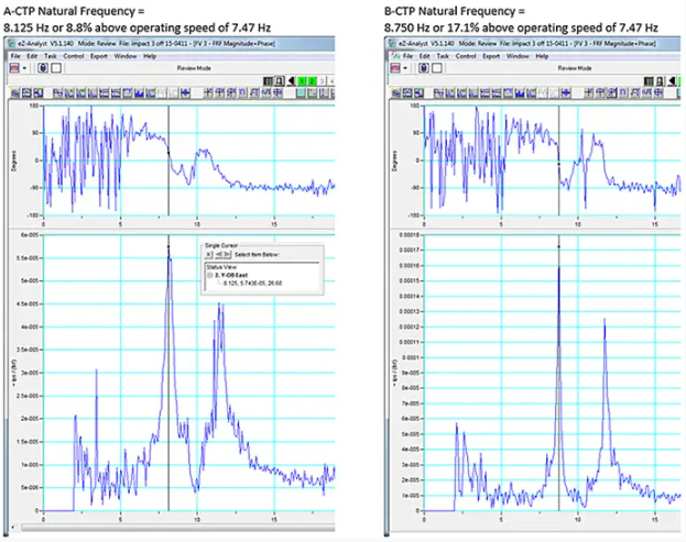
Two new 2,682 horsepower (hp), 448 rotations per minute (rpm), 92,600 gallons per minute (gpm), vertical circulating water pumps were installed as part of a new plant construction project (see Image 1). One pump operated smoothly while the other had 28 mils peak to peak vibration at 1x operating speed. Testing revealed the natural frequency of the smooth pump to be 17 percent above operating speed while the 28 mil pump was only 8 percent (see Figure 1). Both natural frequencies had very high amplification factors. The 28 mils vibration exceeded the allowable limits and natural frequency criteria required in the contract. In this case the EPC and providers worked to aggressively move the natural frequency per the contract language, and the problem was eventually resolved.

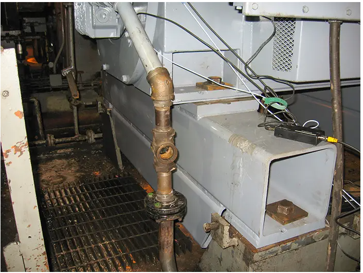
A new 5,500 hp, 3,581 rpm pump motor was purchased to replace a larger frame 1960s vintage motor. Due to the more efficient smaller frame of the new motor, an adapter was fabricated to mount the new motor to the old base. The motor vibration was high due to resonance (see Image 2). There was no natural frequency requirement written into the purchase agreement, but after significant time, testing and educating the provider, a new adapter was provided under warranty (see Image 3). Resonance-specific contract language and design oversight could have avoided
the problem.
Appropriate contract/purchase order language, engineering, modeling, oversight and commissioning is good insurance towards minimizing the risk of a resonance problem. If in-house expertise is limited, then consider using a third party consultant for oversight depending on the specific project. Planning and foresight require effort, but pay off down the road.

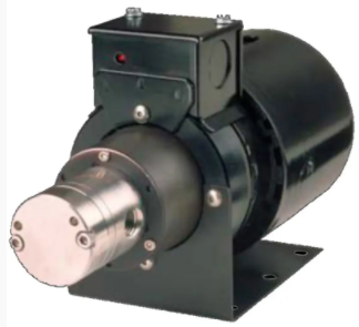
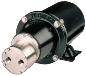
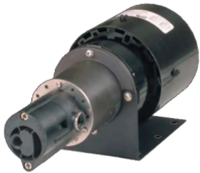
Since 1977, Tuthill has worked to improve magnetically driven gear pumps by engineering solutions to meet the needs of varying applications and exacting designer specifications. The result is a family of magnetically coupled pumps that have found wide industry acceptance for their versatility and robust standards of build and reliability.
These pumps are known for their magnetically coupled, leak-free, seal-less construction and the nonpulsing flow of their external gear design. This makes them perfect for demanding applications such as medical equipment, laboratory equipment, chemical metering, laser cooling, and industrial temperature control. If it requires a seal-free, technically advanced pump, Tuthill Magnetically Coupled Pumps are the solution.
The external gear design offers flow that is relatively independent of pressure providing constant fluid delivery with no pulsations. The flow will have a controlled volume that is accurate and repeatable, making it highly suitable for metering applications. The D, T, & P Series pumps can meet these demands in circumstances with high differential pressures and high system pressures, as well as thin to moderate viscosity fluids. The high volumetric efficiency is achieved by utilizing two identical gears that rotate against each other.
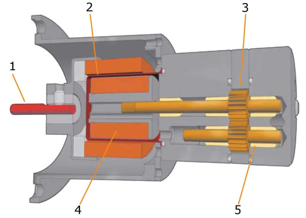
1. Motor End | 2. Magnet Containment No Dynamic Seals | 3. Gears: The Only Moving Parts | 4. Magnetic Coupling | 5. Robust 5 Bearing Design
A vast knowledge of magnet, pump, and motor technology is utilized in the design, manufacturing, and application of our magnetically coupled pumps.
The long life and non-pulsing flow of the external gear design are combined with the magnetically coupled, leak-free, seal less construction. Temperatures to 350°F (176°C) and viscosities from 0.3 cps to over 10,000 cps make this pump tough and reliable.
The P Series magnetically coupled external gear pumps are constructed with Polyphenylene Sulfide (PPS), a highly durable engineered plastic.
The PPS pumps produce a consistent non-pulsing flow, providing a versatile and durable solution in many applications.
| Displacement | Pump | Maximum Speed | Maximum Differential Pressure | Maximum Temperature | Flow @ 0 Pressure | |||||
|---|---|---|---|---|---|---|---|---|---|---|
| Intermittent | Continuous | 3500 RPM | 2900 RPM | |||||||
| ML/REV | SERIES | RPM | PSI | BAR | PSI | BAR | °F | °C | GPH | LPH |
| .11 | D | 5000 | 250 | 17.2 | 250 | 17.2 | 350 | 177 | 6 | 18 |
| .19 | D | 5000 | 250 | 17.2 | 250 | 17.2 | 350 | 177 | 10 | 31 |
| .23 | D | 5000 | 250 | 17.2 | 250 | 17.2 | 350 | 177 | 12 | 38 |
| .38 | D | 5000 | 250 | 17.2 | 250 | 17.2 | 350 | 177 | 20 | 63 |
| .57 | D | 5000 | 250 | 17.2 | 250 | 17.2 | 350 | 177 | 30 | 94 |
| .68 | D | 5000 | 250 | 17.2 | 200 | 13.8 | 350 | 177 | 35 | 112 |
| .80 | D | 5000 | 250 | 17.2 | 200 | 13.8 | 350 | 177 | 42 | 132 |
| .99 | D | 5000 | 200 | 13.8 | 140 | 9.7 | 350 | 177 | 52 | 164 |
| 1.2 | D | 5000 | 200 | 13.8 | 140 | 9.7 | 350 | 177 | 63 | 198 |
| 1.3 | D | 5000 | 175 | 12.1 | 125 | 8.6 | 350 | 177 | 68 | 215 |
| 1.6 | D | 5000 | 150 | 10.3 | 100 | 6.9 | 350 | 177 | 84 | 264 |
| 2.0 | D | 5000 | 150 | 10.3 | 100 | 6.9 | 350 | 177 | 105 | 331 |
| 2.3 | D | 5000 | 150 | 10.3 | 100 | 6.9 | 350 | 177 | 121 | 380 |
| 2.6 | T | 5000 | 250 | 17.2 | 150 | 10.3 | 350 | 177 | 137 | 430 |
| 5.3 | T | 5000 | 145 | 10 | 100 | 6.9 | 350 | 177 | 279 | 876 |
| 7.9 | T | 4000 | 95 | 6.6 | 70 | 4.8 | 350 | 177 | 416 | 1306 |
| 8.0 | T | 4000 | 150 | 10.3 | 125 | 8.6 | 350 | 177 | 421 | 1343 |
| 12. | T | 4000 | 120 | 8.2 | 100 | 6.9 | 350 | 177 | 650 | 2015 |
| .38 | P | 4000 | 130 | 9.0 | 130 | 9.0 | 150 | 66 | 20 | 63 |
| .57 | P | 4000 | 110 | 7.6 | 110 | 7.6 | 150 | 66 | 30 | 94 |
| .68 | P | 4000 | 90 | 6.2 | 90 | 6.2 | 150 | 66 | 36 | 112 |
| 1.2 | P | 4000 | 70 | 4.8 | 70 | 4.8 | 150 | 66 | 63 | 198 |
| Legend | Constant Duty at Maximum Pressure | Intermittent Duty at Maximum Pressure | ||||||||
*Flow rates may vary depending upon application.
| D Series | T Series | P Series | |
|---|---|---|---|
| Wetted Components | 316 SS, Hastelloy, or Titanium | 316 SS, Hastelloy, or Titanium | PPS with 316 SS, Hastelloy, or Titanium Trim |
| Gears | PPS, PEEK, or LCP | PPS or PEEK | PPS |
| Bearings | PPS, PEEK, or LCP | PPS or PEEK | PPS |
| O-Rings | Viton, PTFE, EPR, Nitrile, or Neoprene | Viton, PTFE, EPR, Nitrile, or Neoprene | Viton, EPR, Nitrile, or Neoprene |
| Magnets | Encapsulated Ceramic or Samarium Cobalt | Encapsulated Samarium Cobalt | Encapsulated Ceramic or Samarium Cobalt |
316 SS = Stainless Steel | PPS = Polyphenylene Sulfide | PEEK = PolyEtherEtherKetone | EPR = Ethylene Propylene Rubber | LCP = Liquid Crystal Polymer
Tuthill Pump Group has been providing positive displacement lubrication pumps for demanding OEM applications since 1927. Since that time, our product portfolio has developed to expand into a variety of markets and applications. Tuthill Pump products successfully handle applications from an extremely low-flow capacity with a high level of accuracy, to applications that are nearly solid in consistency with abrasive characteristics. Contact Us