
You’ll enjoy the All-Pumps experience. We’re certain.
A new mine in Central West NSW needs reliable pumps that can provide them with fire water and solve their water supply issues.
All Pumps worked closely with the hydraulic consultants to provide fire hydrant systems & centrifugal pumps.
The centrifugal pump is the most used pump type in the world. The principle is simple, well-described and thoroughly tested, and the pump is robust and can be effective.
All Pumps distributes many different types of centrifugal pumps to suit a wide range of applications in building services, industry, petrochemical, food and marine uses, with major manufacturers including Griswold, Southern Cross, Inoxpa, Ebara and Regent.
All Pumps also manufactures and supplies the Kwikflo range of custom-built fire service pumpsets to suit a variety of applications and are available with diesel or electric drive options, developed for the increasing demand in fully standard compliant specialised turn-key systems. Built from high-quality, reliable and proven components, these packages greatly simplify the installation of fire protection systems.
Further reading: Centrifugal Pumps
Further reading: Fire Hydrant Systems
Located in Grand Terrace, California, Griswold Pump Company is a full-featured manufacturing facility providing a broad range of pumps for oil & gas, chemical process, industrial, and municipal applications. Griswold designs, engineers, and manufactures a variety of pumps including ANSI, end suction centrifugal, and self-priming. Know More
The centrifugal pump is the most used pump type in the world. The principle is simple, well-described and thoroughly tested, and the pump is robust, effective and relatively inexpensive to produce.
The centrifugal pump creates an increase in pressure by transferring mechanical energy from the motor to the fluid through the rotating impeller. The fluid flows from the inlet to the impeller centre and out along its blades. The centrifugal force hereby increases the fluid velocity and consequently also the kinetic energy is transformed into pressure.
All Pumps distributes many different types of centrifugal pumps, including ANSI centrifugal pumps, to suit a wide range of applications in building services, industry, petro-chemical, food and marine uses, with major manufacturers including Griswold, Southern Cross, Inoxpa, Ebara and Regent. Know More

All Pumps supplied drinking and cooling water to a poultry farm.
Hydroprime self-priming trash pump pumped water from a river 3km away to the farm’s water tank. Javelin multistage pumps were then used to distribute water to different poultry sheds.
Multistage pumps are preferred across applications where liquids require transportation at high pressure by using multiple impellers or stages in the pump body.
For further reading: Javelin Multistage Pumps


Multistage pumps refer to the different stages of pumping in the process of forcing liquid, typically water, through its components. They are common across applications where liquids need to be transported with high pressure, achieving this with the use of multiple impellers or stages in the body of the pump.
All Pumps offers a wide range of multistage pumps, and has experience and expertise in hundreds of different applications of this type of pump. Know More
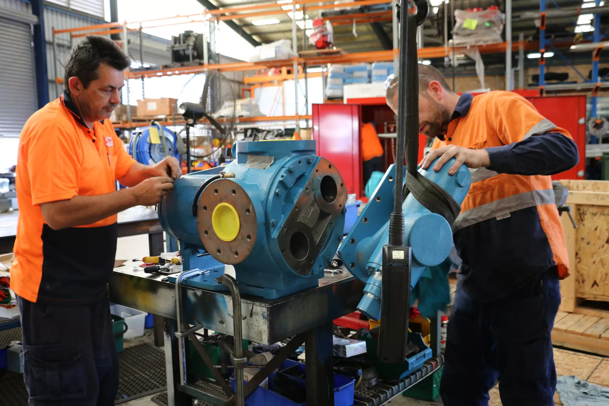
Any equipment requires regular maintenance to keep it running smoothly. A pump that performs rigorous work every day needs scheduled inspections to ensure its settings, such as shaft or belt alignment, are kept within industry tolerances.
This blog will review the common misalignment issues in pumps and how they can be corrected.
Power is transmitted from a motor to a pump by connecting the motor and pump shafts. They can be directly connected using a straight shaft or joined together by a flexible coupling. In some systems, belts are also used between the motor and the pump or the motor and the coupling.
Misaligned shafts lead to costly and unplanned downtime. They also often result in damaged seals. Consequently, broken seals can cause lubrication problems and leaks.
Other potential problems caused by misalignment that can seriously impact a company’s bottom line include:
Looking at these issues, shaft misalignment should be detected and corrected immediately. The stress that misalignment poses on pumps can trigger bigger problems than mere seal and coupling failure. In worst cases, unattended shaft misalignment can cause permanent damage to both the pump and motor, leading to a costly replacement.
With the current challenge in reducing costs and optimising assets, the necessity of accurate shaft alignment has never been greater. Shaft misalignment is responsible for as much as 50 per cent of pump breakdown costs. Thus, by aligning shafts correctly, these costs can be reduced significantly, as well as unplanned downtimes resulting in production loss.
There are several ways to detect and correct improperly aligned shafts. The most common methods include:

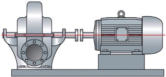
Laser alignment uses two sensors placed on two connected shafts. The sensors fire lasers and receive the other sensor's beam simultaneously. Comparing the laser beams reveals whether the shafts are aligned and within a specified tolerance.
A more advanced laser shaft alignment system comes with a built-in step-by-step alignment process, from preparation, inspection and evaluation through correction, reporting and analysis. Some models also offer a unique database to store data regarding visual inspections on oil leakage, oil level, foundation bolt status, and wear indications.
Laser-alignment methods represent a marked improvement over traditional methods. Laser-guided tools allow one to adjust shaft alignment faster and more accurately than the straightedge or dial method.
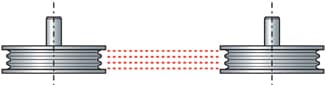
Indirect drives use gears or pulleys and belts or chains to offset the motor shaft from the pump shaft. In belt and pulley alignment, the grooves of the pulleys are placed in line with one another. Done correctly, there will be low risks of premature wear for the belt and energy loss for the pump or motor.
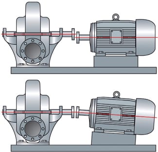
As with shaft misalignment, there are various types of belt misalignment. The following illustrations show the three different types of belt misalignment.
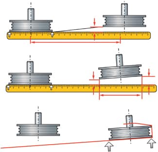
1.Vertical angle or twisted misalignment occurs when one of the pulleys has an angular error from the vertical angle plane. This is usually caused by incorrect positioning of the pump. This problem can be corrected by lifting either the front or rear feet of the motor to which the pulley is attached, depending on the direction of the vertical angle error.
2.Horizontal angle misalignment occurs when the driver and the driven unit are not parallel to each other. Horizontal angle misalignment can be corrected by moving the front or rear feet forward or backward to their guides, depending on the direction of the horizontal angle error, to twist the motor around its centre.
3.Parallel misalignment is the least complex form of misalignment. It is often caused by the incorrect positioning of the motor along its shaft axis, positioned either too far forward or backward compared to the other shaft. Or it can be caused by incorrect positioning of the pulleys on their respective shaft, where one of the pulleys needs to be adjusted on the shaft.
Like shaft alignment, belt alignment can be done by a traditional visual or laser alignment method. Traditional methods usually employ strings or straightedges. Laser methods utilise laser beams, which provide a much higher degree of accuracy.
Laser alignment tools on the market can be categorised according to how the devices are attached to the pulley and how they align. Generally, there are two groups - one that aligns the face of the pulleys and one that aligns the grooves.
Most laser alignment tools use the face or side of the pulley as a reference for aligning the pulleys and belts. The advantage of this method is that it can be used for belt types other than V-belts, such as timing belts. However, V-belts are the most commonly used type in industrial applications.
The main disadvantage is that the face of the pulley is the only reference point. This method results in varying degrees of accuracy when the pulleys are of different thickness, brands, kinds (e.g. one single-belt pulley and one multiple-belt pulley) or when the faces are not well finished.
Products that align using the grooves of the pulleys provide substantially higher levels of accuracy regardless of the thickness, brand or type of pulleys.
Shaft and belt misalignment can be a result of several factors such as:
Other possible causes include:
Noise and vibrations are the first indications of a running pumping system problems. Vibration analysis, performed as part of a preventative maintenance and monitoring programme, can identify if shaft misalignment is becoming a problem. Rapid detection of misalignment in this way can save a pumping system from damage.
Once shaft or belt misalignment is detected, analysed and corrected, an ongoing alignment maintenance program is important to keep operations running smoothly. As part of this maintenance, alignment checks should be performed to document alignment conditions before a machine is removed from service. This gives users the ability to install new or rebuilt machines with the same proper alignment values. In addition, a maintenance program should include periodic checks to verify conditions are still within tolerance.
Taking these simple steps to detect, correct and maintain proper shaft and belt alignment can prevent costly, unplanned downtime. Fortunately, there is a range of modern laser-alignment options available to make this process easier.
Reduce these breakdowns, production losses, high energy consumption, overheating, excessive vibration, and premature wear and tear with our laser alignment services.
All-Pumps have qualified experts well-positioned to perform laser alignment services using the latest SKF shaft alignment tools to achieve the highest accuracy. We also provide a detailed Laser Alignment Report for your reference after service completion.
We can work to fix:
Chemical manufacture includes some of the most complex industrial processes in the world. In fact, chemical-manufacturing processes can be so intricate that there are several “unit operations” within an overall process. These may include cracking, distillation and evaporation, gas absorption, scrubbing and solvent extraction, among others.
Within that family of unit operations, there is one that stands out above the others in its importance to the total manufacturing process: Transferring. Simply put, transferring is nothing more than the process of transporting fluid from one point to another. In the real world of chemical manufacturing, however, transferring is so much more.
While many unit operations in chemical manufacturing pertain to one specific application within a much greater whole, fluid transfer is a jack-of-all-trades, with responsibilities all along the chemical-production chain. Due to the importance of the myriad transferring operations within the chemical-manufacturing process, facility operators must identify the best pumping technology for the job, one that possesses the versatility to perform reliably and efficiently at any number of points in the production regime.
For many years, the go-to technology for the chemical-transfer process has been the centrifugal pump, for a few reasons:
In reality, positive displacement (PD) pump technologies, most notably the sliding vane and eccentric disc varieties, can counteract the supposed advantages offered by centrifugal pumps:
Maybe most importantly, unlike centrifugal pumps, the design of PD pumps allows them to produce a constant flow at a given speed, no matter what the application’s discharge pressure is. In other words, PD pumps are constant-flow machines, which is critical since most chemical-manufacture applications require precise dosing rates.
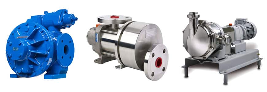
Two operating companies within the Pump Solutions Group (PSG), offer sliding vane or eccentric disc pump technologies that have been designed to be a front-of-mind choice in chemical-transfer applications: Blackmer®, Grand Rapids, MI, USA, and Mouvex®, Auxerre, France.
Blackmer offers the SNP Series Sliding Vane Pump, a stainless-steel model ideal for handling a wide variety of corrosive or caustic fluids with varying viscosities. Mouvex features a pair of pump models for chemical-transfer applications: the A-Series, which maintain its initial performance level over time without any adjustment, thanks to an automatic clearance make-up system; and the SLC Series, a seal-less, all-stainless-steel model with a double bellows that ensures durability, safety and total product containment.
For years, centrifugal pumps have proven to be reliable workhorses in many aspects of chemical manufacturing, but when the fluid-transferring process is looked at specifically, the benefits of centrifugal pump performance begin to wane. That’s why, for fluid transfer in chemical manufacturing, plant operators should be willing to consider PD pumps for their fluid-handling needs. Their overall design and method of operation make them ideal for a wide array of transfer applications, while they will also help optimize the bottom line.
Mouvex, founded in 1906, is a major manufacturer of eccentric disc pumps which is used in major applications across various types of industries. Due to its unique design, eccentric disc pumps are able to transfer viscous, non-lubricating, volatile and delicate materials without any risk of shearing.
Many of these units have provided 30 or 40 years of service with virtually no maintenance.
All Pumps supply the complete range of genuine Mouvex pumps and spare parts at competitive price levels. Know More
The centrifugal pump is the most used pump type in the world. The principle is simple, well-described and thoroughly tested, and the pump is robust, effective and relatively inexpensive to produce.
The centrifugal pump creates an increase in pressure by transferring mechanical energy from the motor to the fluid through the rotating impeller. The fluid flows from the inlet to the impeller centre and out along its blades. The centrifugal force hereby increases the fluid velocity and consequently also the kinetic energy is transformed to pressure.
All Pumps distributes many different types of centrifugal pumps, including ANSI centrifugal pumps, to suit a wide range of applications in building services, industry, petro-chemical, food and marine uses, with major manufacturers including Griswold, Southern Cross, Inoxpa, Ebara and Regent. Know More

All Pumps supplied a Graco Air Operated Diaphragm (AOD) Pump for a customer who need it for emergency spills and bilge water.
The perfect pump for the job is a Graco AOD pump as it
Without a large capital outlay, this customer has made his response to these emergencies faster and easier.
Air Operated Pumps are perfect for pumping almost any substance including chemicals, fresh/salt water, oils, paints, sludge and even small solids – a great all-rounder.
Contact All Pumps now for all your fluid handling solutions.

The industrial pump is a slave to the pumping system. The system governs the pump. The system is composed of the suction and discharge vessels plus all pipes, elbows, valves, filters, fittings, and instrumentation. The pump reacts when the system changes.
If the pump is forced to do what it cannot do, then it fails frequently and prematurely. We call it mysterious pump failure, reactive maintenance, or unscheduled downtime. So, how do you know what your pump can do within the system?
The answer is simple, but not always realistic. The pump curve should be available and understood by everyone involved with the pump, although it rarely is.
You can get some good information off the pump and motor ID plates. The motor ID plate indicates the speed. The pump ID plate normally indicates the impeller diameter in inches.
With the pump speed and the impeller diameter, you can approach it in 2 ways.
At 1,800 RPM, the impeller diameter in inches, multiplied by itself, is the approximate shutoff head of the pump in feet. This means that a standard centrifugal pump with a six-inch impeller on a four-pole motor will generate 34 to 38 ft. of shutoff head (6 x 6 = 36).
Likewise, a nine-inch impeller on a four-pole motor would generate about 80 ft. of shutoff head (9 x 9 = 81). And a 13-inch impeller would generate about 170 ft. of shutoff head (13 x 13 = 169). These numbers are accurate within about 5 percent.
The best efficiency point (BEP) is about 85 percent of the shutoff head. The pump should be operated at, or close to, the best efficiency point.
The key word here is “about.” This method has exceptions, depending on the pump design, application, and liquid. However, this covers about 90 percent of all centrifugal pumps. If the pump speed or impeller diameter changes, the pump performance varies by what are commonly referred to as the affinity laws.
The shutoff head is a simple concept. If you were to pump into a vertical pipe, the pump would push the liquid up into the pipe to a certain point beyond which no more elevation could be obtained. Flow becomes zero as all the energy of the electric motor is invested into maintaining elevation. This is the shutoff head.
Assuming you have a pump to fill a tank at 600 GPM with ambient water, the discharge pipe rises over the top of the tank and drops down into the tank.
When full, the level in the discharge vessel is 52 ft. above the level in the suction vessel. The system has two feet of friction losses with the pipe runs, the elbows, valves, and instrumentation.

The important elements of a typical centrifugal pump curve plotted on a graph. The vertical axis reads head or elevation in feet starting at 0. The horizontal axis reads flow in GPM starting at 0.
How would you specify a pump for this system? The pump must generate 54 ft. of head (52 ft. elevation change plus two feet friction losses) at 600 GPM. Your pump impeller diameter should be eight inches mated to a four-pole electric motor. The shutoff head would be approximately 64 ft. The BEP would be about 54 ft. (85 percent) at 600 GPM.
The BEP for a typical centrifugal pump is noted on the curve in the figure provided above with coordinates drawn to point C (best efficiency head in feet) and point D (best efficiency flow in GPM).
How would you know if this pump is performing as it should?
Ambient water at 54 ft. would convert into 23 PSI differential on the pump’s pressure gauges. If the suction gauge reads zero PSI, the discharge gauge should read 23 PSI. A flowmeter might report a velocity that converts to 600 GPM. It’s that easy. It also shows the importance of the instrumentation tech to pump reliability. Pumps need working gauges. Equipment operators need training to properly interpret them.

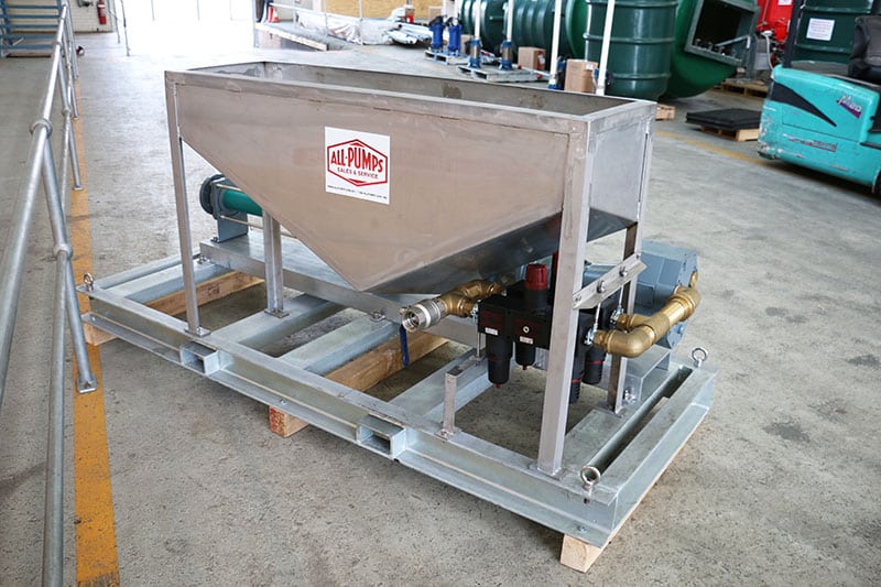
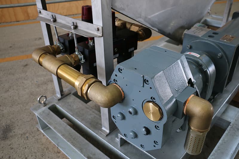
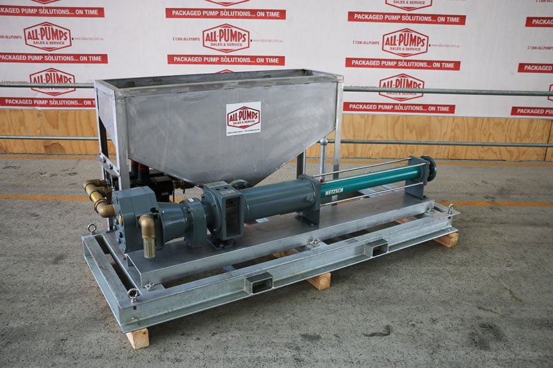
All Pumps was recently approached to supply a pump which will be used for transferring construction application, such as grout.
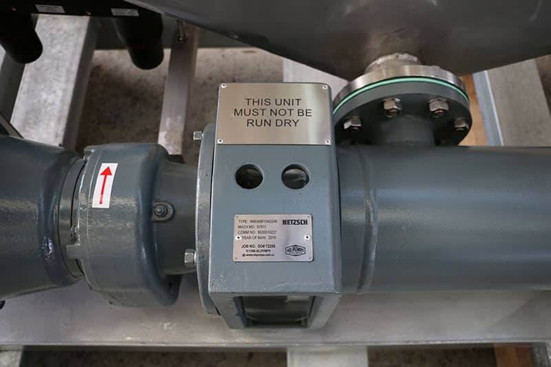
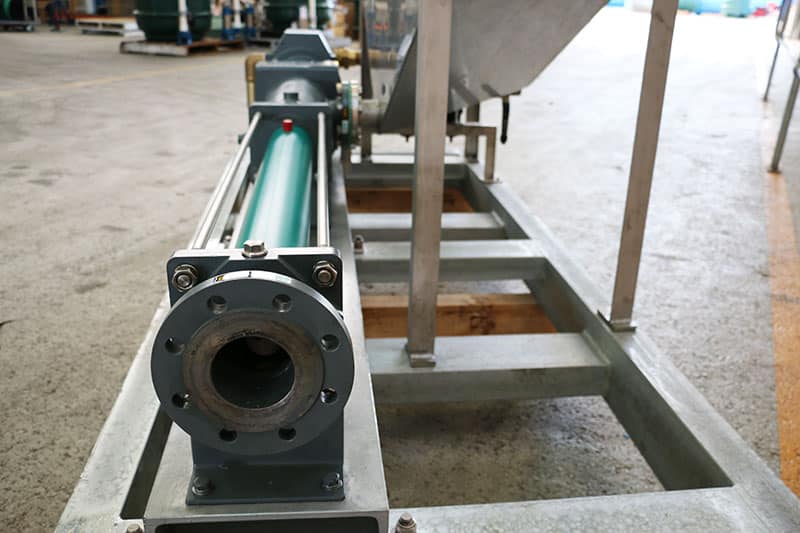
A Netzsch NEMO NM045 air-operated progressive cavity pump was customised and supplied.
It has a 3 inch discharge outlet, coupled with SS side feed grout hopper and installed on a compact galvanized skid.
All Pumps product range of Netzsch progressive cavity pumps covers everything from the smallest dosing pumps conveying a few millilitres to large pumps for up to 1000m³/h.
Progressive cavity pumps are positive displacement rotating pumps which have an almost pulsation-free liquid flow and are ideal for pumping liquids from those as thin as water to those with high viscosity, with or without solids.
Also known as helical rotor pumps, these pumps are capable of pumping viscous or shear-sensitive materials.
Netzsch Progressive Cavity Pumps

Australia’s Biggest Morning Tea is an opportunity for friends, family or workmates to come together and raise funds for the Cancer Council.
This is a great event and we were privileged to be part of it.
Do you know that 1 in 2 Australian men and 1 in 3 Australian women will be diagnosed with cancer by the age of 85?
By donating one dollar at a time you are making a real difference helping to fund Cancer Council’s vital research, prevention and support service programmes.
See how your money helps – www.biggestmorningtea.com.au/about-the-event/how-your-money-helps

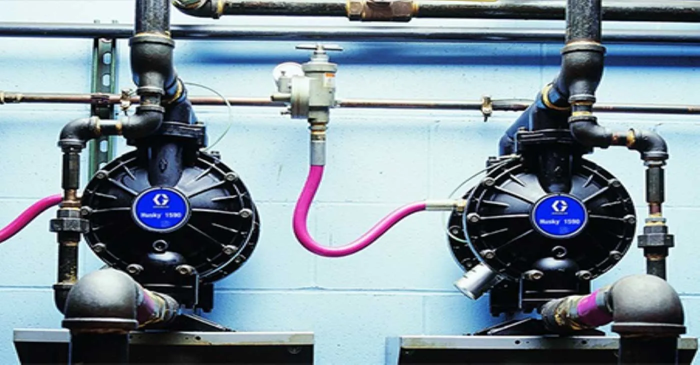
AODD pumps(also known as Air operated diaphragms pumps, pneumatic diaphragm pumps, AODD pumps, AOD pumps) are used for endless applications in mining, industrial and general plant service. Powered only by compressed air, they are especially used where electricity isn’t available, or in explosive or flammable areas.
AOD pumps are a type of reciprocating diaphragm pump which contains two diaphragms driven by compressed air. Air section with shuttle valve applies air alternately to the two diaphragms, each diaphragm has a set of check/ball valves.
In this post, we will explore the operation principle of AODD pumps.