
You’ll enjoy the All-Pumps experience. We’re certain.

Reducing the temperature in the seal chamber offers many benefits to the performance and reliability of a mechanical seal operating in hot service. This is one of the most effective ways to increase the vapor pressure margin and prevent the pumped fluid from flashing in the seal chamber or at the interface of the mechanical seal’s faces. Additionally, lowering the seal chamber temperature also increases the fluid’s viscosity, providing a more stable fluid film at the interface of the seal faces.
One method of achieving a reduction in temperature is to circulate fluid from the seal chamber through a heat exchanger and return the cooled fluid back into the seal chamber. The heat exchanger is often referred to as a “seal cooler” since it is not part of the process, but just an auxiliary system component. This piping arrangement is known as an API Plan 23. When installed, operated and maintained correctly, a Plan 23 is one of the most effective methods of lowering the seal chamber temperature.
Fluid is circulated through the heat exchanger by a pumping ring incorporated into the mechanical seal’s design. The pumping ring, typically a slotted wheel or helical scroll, is spinning with the pump shaft and functions as a miniature pump within the seal chamber. In comparison to the main impeller on the pump shaft, the pumping ring only generates an extremely small fraction of pressure head and flow. Thus, it is of critical importance that the design, selection and installation of the flow circuit is optimized to provide the least resistance to flow, thereby maximizing the circulation rate and the ability of heat energy to be transferred from the seal chamber to the heat exchanger.
There are three main elements to the flow circuit that can be optimized:
The heat exchanger needs to be of a suitable size to dissipate the heat load placed on it while offering minimal resistance to flow. Water-cooled shell and tube heat exchangers meet these requirements and are often the first choice for a heat exchanger design. Plate-style heat exchangers, although compact and with large heat transfer rates, should be avoided as their resistance to flow is high. Air-cooled heat exchangers can be used in water constrained installations. However careful design and selection is required to meet the cooling capacity needed while not being excessively large.
The preferred method to connect the heat exchanger to the seal chamber is using drawn tubing (where codes and standards allow). The diameter should match that of the heat exchanger coil. If in doubt, a larger size should be selected. Note that excessively large sizes will not yield positive results and may be detrimental to lowering the flow resistance of the circuit. To minimize the resistance to flow in the tubing, valves should be avoided. If they are required, they should be full-ported gate type or locking ¼-turn ball valves. The number of bends in the tubing should also be minimized, only using long radius bends and avoiding the use of short 90-degree fittings. The overall length of the tubing run should be kept to a minimum.
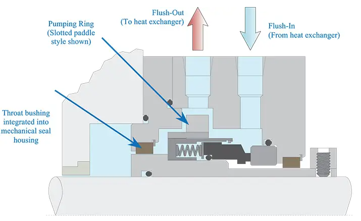
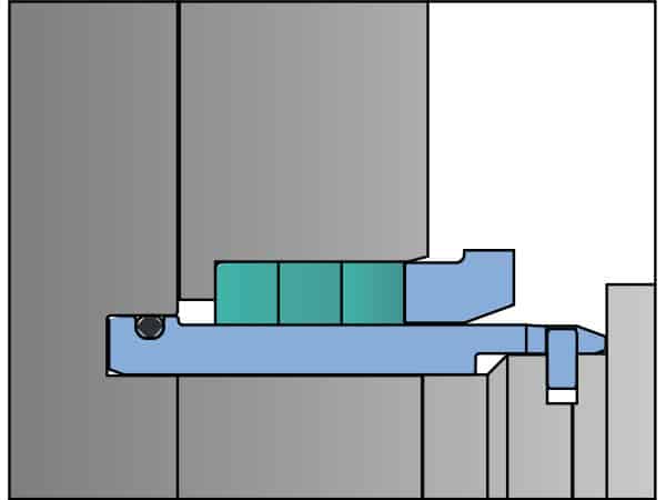
Where sufficient space exists in the seal chamber, the most efficient pumping ring designs and the flush ports delivering fluid to and from the pumping ring are designed as an integral part of the mechanical seal and its housing (see Figure 1). This allows the seal manufacturer to optimize the location of the flush ports to gain the maximum pressure and flow from the pumping ring. It also enables the correct cooling flow path through the mechanical seal, ensuring cool fluid is delivered to the mechanical seal faces.
For pumps with horizontal shafts, the flush-out port should be located at the top of the seal housing to enable the seal chamber to be vented of any trapped gases, and the flush-in port located at or below the shaft centerline. Vertical shafts should have the flush-out port at the uppermost point in the seal chamber to achieve complete venting. This typically necessitates the use of an axial flow pumping ring with the flush-in port located below the pumping ring.
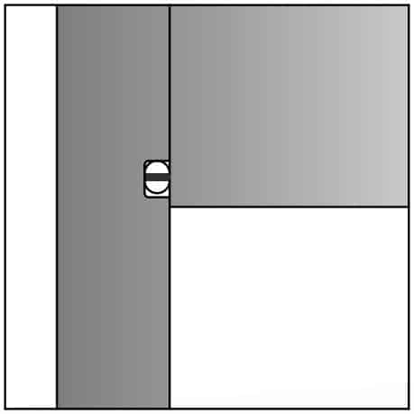
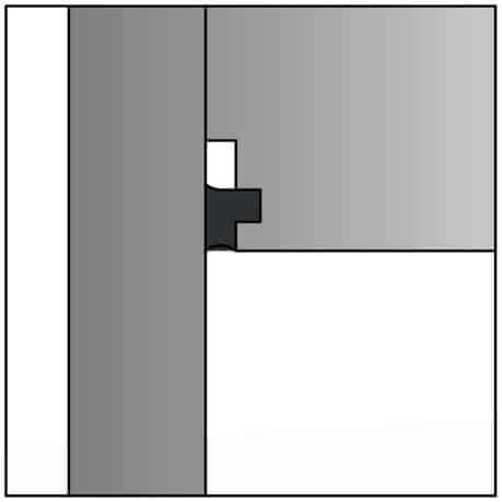
Since the Plan 23 flow circuit is not truly a closed loop, loss of cooled fluid in the seal chamber occurs as fluid enters and exits the seal chamber throat. This mixing of hot fluid from the pump and cooled fluid in the seal chamber can be minimized by the addition of a close clearance seal chamber throat bushing. A fixed bushing is suitable in most cases. However, tighter clearances can be achieved with the use of a floating bushing. It is a good practice to run floating bushings against a renewable surface, such as a sleeve, rather than against the pump’s bare shaft. This bushing can be integrated into the design of the mechanical seal or installed as a separate item into the throat of the seal chamber. When installed as a separate item, the bushing should be renewed with each mechanical seal change to minimize mixing of hot and cold fluids in the seal chamber. The retention method of the bushing must consider the temperature differences of the pump casing, which will be close to process temperature, and the bushing parts that are closer to the much lower seal temperature.
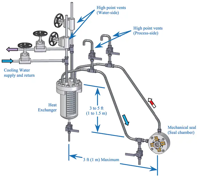
The heat exchanger should be mounted in a position above and to the side of the mechanical seal so that short direct tubing runs can be made to connect the seal chamber (or mechanical seal) flush ports to the heat exchanger.
Mounting the heat exchanger at or near the maximum height noted in Figure 2 can enhance thermosyphoning (flow induced by the small difference in density of the hot fluid entering the heat exchanger and cool fluid exiting). This can assist the flow from the pumping ring while the pump is operating and continue to create flow while the pump is idle.
The interconnecting tubing between the seal chamber (or mechanical seal) flush ports and the heat exchanger should slope upwards towards a high point vent at a minimum slope of 0.5 inches per foot (40 millimeters per meter). As the interconnecting tubing will be hot during operation, the potential for contact burn injuries to maintenance and operation personnel is present. Expanded mesh heat guards are the preferred method of mitigating burn hazards since they allow natural heat convection to occur from the exposed tubing. For installations where space is tight, mechanical insulation can be used to mitigate the hazards.
The orientation of the heat exchanger should be selected so that any air trapped in the cooling coils can naturally flow to a high point and be vented. The location and height of the heat exchanger should be selected so that it facilitates access for servicing the heat exchanger while minimizing the impact of access to the pump for maintenance. The heat exchanger should never be mounted directly over the pump or motor.
Prior to starting the pump, the process and water side of the heat exchanger need to be vented of any trapped air or vapor. High point vents fitted to both the cooling water and process piping facilitate the venting. Venting of the process side also vents the heat exchanger, the seal chamber and the interconnecting tubing. Process side venting often requires special sizing and routing considerations depending on fluid properties, system pressure, temperature and hazards. The design must ensure effective venting capability while maintaining safe operation.
Cleaning the heat exchanger should be performed when loss of efficiency is apparent. Normally, this results from fouling of the cooling water side of the heat exchanger. The rate at which fouling occurs depends on the quality of the cooling water and the heat load placed on the heat exchanger. Areas with hard water will require frequent cleaning of the heat exchanger to remove mineral scale. The heat exchanger should be cleaned at every seal change.
For these situations, alternative cooling methods such as API Plan 21 or Plan 32 should be considered. The need for seal chamber cooling can also be eliminated by the use of a dual pressurized seal.
API Plan 23 provides an effective method of controlling the seal chamber temperature around the mechanical seal. This reduction in seal chamber temperature can suppress vaporization and improve the properties of the fluid at the interface of the mechanical seal faces resulting in improved seal reliability.

The objective of this project was to address the odour complaints coming from nearby residents, and after a detailed options study, it was decided to construct two facilities at either end of a main trunk section, spanning the entire length of a road in Suburban South Australia.
The odour control system was required to provide treatment for 2000m3/hr of foul air containing 500ppm of hydrogen sulphide (H2S) and other harmful gases (VOCs and RSCs), with peak concentrations of H2S of up to 1000ppm.
All-Pumps Environmental projects team were required to guarantee 99.5% removal of the H2S gas, and therefore selected a system containing a Biotricking Filter, Biofilter, and Activated Carbon Filter to ensure total removal of odours.
With our extensive experience in FRP manufacturing, and process know-how backed by our partner BIOREM Technologies, All-Pumps was able to meet the delivery expectations of the client and the performance requirements of the project. The success of the project was further enhanced by our relationship with a key preferred contractor in South Australia.
All Pumps manufactures and supplies the Kwikflo range of pumps, pumping equipment and systems, including associated accessories and options for a variety of industry groups including Building Services, Civil and Construction, Mining, Fire Protection, Environmental and Rainwater Harvesting.
All Pumps has these pumps and parts in stock and is ready to help with your requirements today.

Jabsco has a proven 50 year heritage in Lobe Pump manufacturing. Jabsco branded lobe pumps are taking the next step in flexibility and value. The Hy~Line+ (HP Series) and Ultra~line (UL Series) range of lobe pumps replace the Hy~Line, Ultima and 24 Series lobe pumps offering the combined strengths and experience on one key platform.

The standard offering for compatible fluids

For fluids with the potential to leave a residue; ATEX applications

For fluids that must not escape to the atmosphere
Low-cost alternative to handle fluids with the potential to leave residue
| Seal Type | Primary Seal Face Options | 2nd Seal Face | Available on | ||
|---|---|---|---|---|---|
| Single Seal Mechanical | C/SS | C/SiC | SiC/SiC | – | Size 3 to 7 |
| Single Seal Mechanical (Flush option) | C/SiC | SiC/SiC | C/SiC | Size 3 to 7 | |
| Double Mechanical Seal (integral flush) | C/SiC | SiC/SiC | C/SiC | Size 4 to 7 | |
| 3 ring packed gland | – | – | – | – | Size 4 & 5 |
| Configuration | Realisation |
|---|---|
| Horizontal ports | Apply Horizontal foot kit |
| Top shaft drive | Comes as standard |
| Bottom shaft drive | Rotate gear cover 180°, swap filler cap and sight glass |
| Vertical ports | Apply vertical foot kit |
| Left shaft drive | Swap filler cap and sight glass |
| Right shaft drive | Rotate gear cover 180°, swap filler cap and sight glass |
Tri-lobe and scimitar rotor options on one pump platform
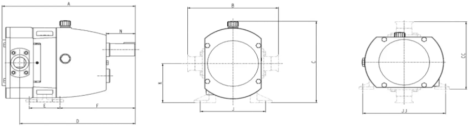
| Pump Size | A | B | C | CC | D | E | F | J | JJ | K | N | Max Speed | Max Pressure | Flow 100rpm | Weight |
|---|---|---|---|---|---|---|---|---|---|---|---|---|---|---|---|
| 42 | 274 | 223 | 212 | 182 | 231 | 72 | 142 | 150 | 200 | 99 | 42 | 1000 RPM | 15 BAR | 12.3 LTR | 18 KG |
| 44 | 290 | 223 | 212 | 182 | 241 | 72 | 142 | 150 | 200 | 99 | 42 | 1000 RPM | 8 BAR | 20.4 LTR | 20 KG |
| 52 | 368 | 249 | 250 | 208 | 319 | 84 | 208 | 179 | 228 | 120 | 80 | 1000 RPM | 15 BAR | 26.5 LTR | 32 KG |
| 54 | 396 | 259 | 250 | 213 | 338 | 84 | 208 | 179 | 228 | 120 | 80 | 1000 RPM | 8 BAR | 45.5 LTR | 35 KG |
| 62 | 433 | 288 | 329 | 249 | 370 | 122 | 224 | 200 | 294 | 174 | 79 | 720 RPM | 15 BAR | 64 LTR | 61 KG |
| 64 | 462 | 302 | 329 | 256 | 379 | 122 | 224 | 200 | 294 | 174 | 79 | 720 RPM | 8 BAR | 95 LTR | 65 KG |
| 72 | 489 | 380 | 381 | 324 | 414 | 210 | 178 | 288 | 342 | 186 | 89 | 680 RPM | 15 BAR | 123 LTR | 125 KG |
| 74 | 529 | 380 | 381 | 324 | 439 | 210 | 178 | 288 | 342 | 186 | 89 | 600 RPM | 8 BAR | 205 LTR | 145 KG |
| 76 | 576 | 411 | 381 | 340 | 456 | 210 | 178 | 288 | 342 | 186 | 89 | 600 RPM | 5 BAR | 301 LTR | 165 KG |
| 84 | 807 | 470 | 484 | 390 | 658 | 268 | 288 | 345 | 440 | 249 | 99 | 600 RPM | 10 BAR | 366 LTR | 370 KG |
Packo represents a legacy of innovation that spans almost 90 years and accounts for millions of quality pumps sold and used around the globe. Now rebranded as Packo under the Verderliquids company, Packo continues to manufacture extremely dependable hygienic rotary lobe pumps. These pumps are industry-preferred for their unequalled quality, hygiene, and durability standards. Their latest rotary lobe pumps incorporate modern technology and the latest hygienic concepts to satisfy the increasing demands for improved cleanability and sterilisation ability.
All Pumps has been importing, servicing and supplying Jabsco pumps in Australia for 20 years and supports the full Jabsco range of pumps and spare parts.
Built On A Time-Tested Design & More Than 90 Years Of Gear Pump Engineering Experience
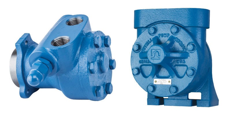
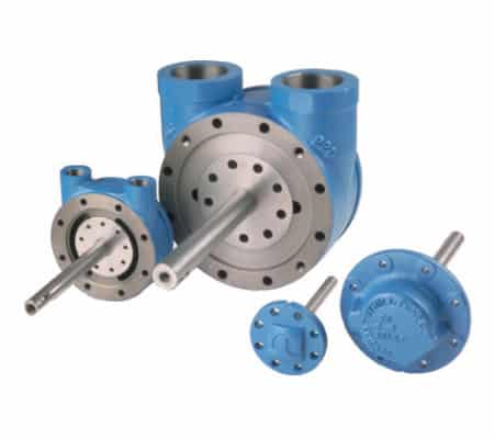
Tuthill offers the Heavy Duty (HD) Series for the most demanding applications – slurries, high viscosity products, suspended solids, concentrated acids, chemicals, high-temperature liquids, sludge, resins, sewage and scum, paints, polymers, plastics, pharmaceuticals, foods, and shear sensitive fluids.
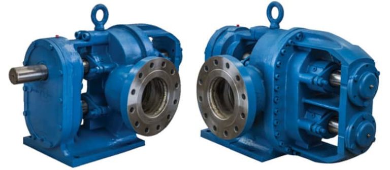
This rotary positive displacement, circumferential piston pump is Tuthill’s severe-duty problem solver. Heavy-duty construction provides longer life in the toughest pumping applications.
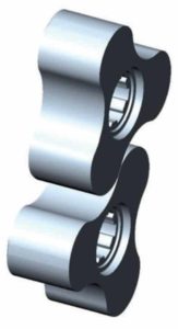
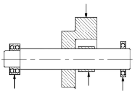
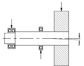
The secret behind the HD Series success is external bearing support on both sides of the impellers which enables the pump to handle high pressure and pressure spikes associated with sudden surges of viscous mass. The load diagrams below show the rigid HD design compared to cantilevered designs with shaft deflections that can result in galling and seizing of the pump.
HD Pumps are very versatile and can be customized to meet the requirements of specific applications. Suction and discharge ports can be reversed by changing shaft rotation.
Single lobe impellers provide maximum strength for highly viscous fluids and slurries, along with high discharge pressure and minimal shear characteristics on fluids


Cartridge Lip Seal Technology has been successfully applied to a number of HD pump applications to address the requirements of leak free performance with intermittent run dry conditions. Optional power monitors are offered as run dry protection and are recommended for use with single mechanical seals where run dry conditions are possible.
| model | flow rate | Maximum Differential | Maximum Speed | Weight | ||||
|---|---|---|---|---|---|---|---|---|
| GPM | M3/HR | PSI | BAR | RPM | LBS | KG | ||
| 70A | 52 | 12 | 450 | 31.0 | 350 | 280 | 127 | |
| 120A | 105 | 24 | 450 | 31.0 | 350 | 300 | 136 | |
| 330 | 265 | 60 | 450 | 31.0 | 350 | 550 | 249 | |
| 600 | 520 | 118 | 450 | 31.0 | 350 | 900 | 408 | |
CAUTION: The fluid being pumped must always be specified. Applications above 200 PSI (13.8 BAR), 350 ºF (177 ºC), or 200 RPM must be reviewed by Tuthill to insure proper pump selection.
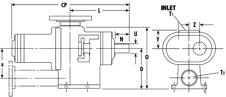
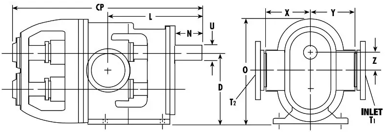
| Model | T1 | T2 | CP | D | L | N | ||||||
|---|---|---|---|---|---|---|---|---|---|---|---|---|
| IN | MM | IN | MM | IN | MM | IN | MM | IN | MM | IN | MM | |
| 70A | 3 | 76 | 2 | 51 | 24 7⁄16 | 620 | 8 1⁄2 | 216 | 12 7⁄8 | 327 | 3 1⁄2 | 89 |
| 120A | 4 | 102 | 3 | 76 | 24 7⁄16 | 620 | 8 1⁄2 | 216 | 12 3⁄8 | 315 | 3 1⁄2 | 89 |
| 330 | 5 | 127 | 4 | 102 | 29 15⁄32 | 748 | 10 3⁄4 | 273 | 14 9⁄32 | 363 | 4 | 102 |
| 600 | 6 | 152 | 6 | 152 | 36 9⁄16 | 929 | 13 3⁄4 | 349 | 18 9⁄16 | 471 | 5 7⁄16 | 138 |
| Model | O | U | X | Y | Z | |||||
|---|---|---|---|---|---|---|---|---|---|---|
| IN | MM | IN | MM | IN | MM | IN | MM | IN | MM | |
| 70A | 13 1⁄4 | 337 | 1 7⁄8 | 48 | 6 1⁄4 | 159 | 4 3⁄4 | 121 | 2 1⁄2 | 64 |
| 120A | 13 1⁄4 | 337 | 1 7⁄8 | 48 | 6 1⁄4 | 159 | 4 3⁄4 | 121 | 2 1⁄2 | 64 |
| 330 | 16 7⁄8 | 429 | 2 1⁄4 | 57 | 8 | 203 | 6 1⁄8 | 156 | 3 3⁄16 | 81 |
| 600 | 20 1⁄4 | 514 | 2 1⁄2 | 64 | 9 | 229 | 9 | 229 | 3 1⁄2 | 89 |
Tuthill Pump Group has been providing positive displacement lubrication pumps for demanding OEM applications since 1927. Since that time, our product portfolio has developed to expand into a variety of markets and applications. Tuthill Pump products successfully handle applications from an extremely low-flow capacity with a high level of accuracy, to applications that are nearly solid in consistency with abrasive characteristics.

In a world of “fake news” it’s definitely harder to figure out what’s real and what isn’t. Since stretching the truth isn’t limited to politics we thought we’d spend some time separating pump fact from pump fiction.
Some vane pump manufacturers frequently blitz trade magazines with articles touting their “superior hydraulic efficiency”. Don’t buy it. Their argument is that since the vanes rub on the case, there isn’t any “slip”. The one thing that they fail to mention though is the relatively high amount of slip that occurs on both ends of the pump between the rotor and side plates. Our helical gear pump has a natural action that pushes the gears against each other and forces one towards the face plate and the other towards the backplate.
This reduces the amount of slip along the sides of the pump. Those of you with old vane pump catalogues will see performance curves that include a slip curve. Several years ago one of the larger manufacturers eliminated the slip curves and only provided curves at specific viscosity points and pressures. The slip is now “built-in” to the actual flow curve and (hopefully for them) invisible. We could do that too but believe it’s more important to provide accurate tools needed to size the pump correctly.
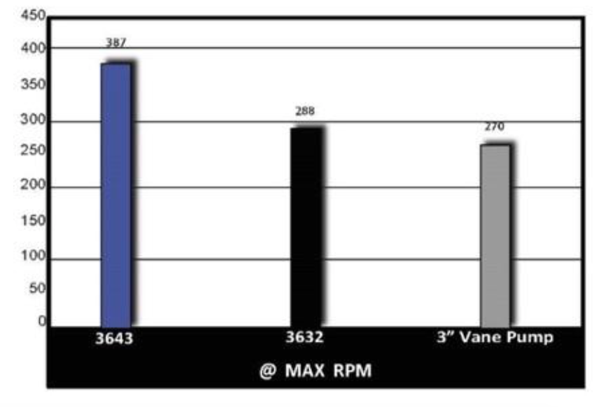
A few years ago we added 2 new pump sizes to the 3600 family that specifically address flow rates versus one of the most common 3” vane pumps in the market. Our models 3632 and 3643 simply out-pump this vane pump. (See graph). On top of that in most cases the 3632 is less expensive than a 3” vane pump and in virtually all cases more forgiving in tough applications.
Roper external gear pumps service a range of industries including engineering, oil, industrial, gas and transport. Made from high-quality cast iron and stainless steel materials, the Roper pump range of products is suited for handling anything from water to the most viscous products such as molasses, oil, chocolate, and tar emulsion among other chemicals. Know More

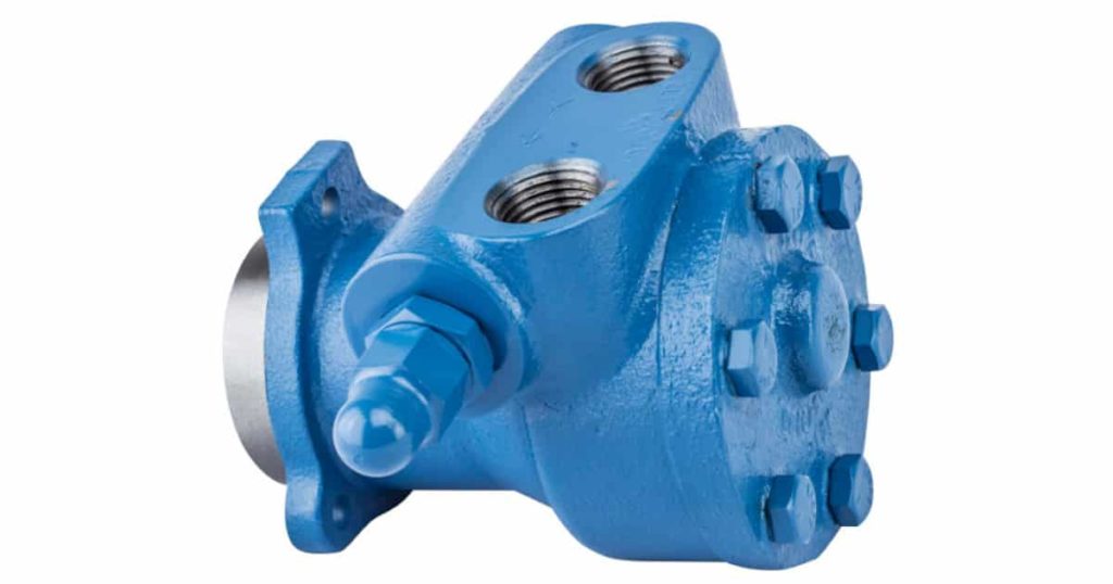
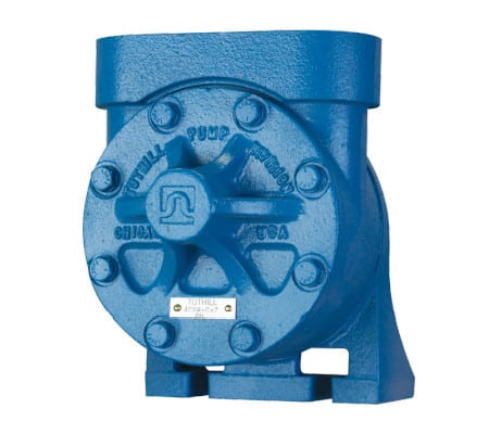
The L & C Series cast iron positive displacement pumps have been the industry standard for Lubrication & Circulation for over 75 years. They were originally designed under James B. Tuthill, the company’s founder. Tuthill has continuously worked to improve these pumps to fit an ever-growing range of lubrication applications. The result is a family of reliable internal gear pumps that are ideal for custom OEM lubrication, low-pressure hydraulics, transfer, circulating, burner oil feed, and many other industrial pump applications.
Performance Ranges
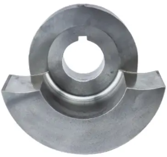
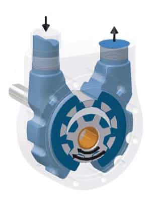
Precisely machined and assembled with only two moving parts, Tuthill L & C series pumps achieve and retain their reliability over a wider range of viscosities than alternative pump designs. L & C series pumps have mounting, driving, and sealing options to suit all your application needs. The pumping action is based on a rotor, idler gear, and a cover cast with a crescent-shaped partition. This design allows the pump to handle a wide range of viscosities while sustaining a constant flow regardless of pressure. The non-pulsating flow also runs substantially quieter than other pump designs. With minimal to moderate wear, our internal gear pumps outperform other pumping technologies.

As the pump starts, the teeth come out of the mesh, increasing the volume. This creates a partial vacuum, drawing the liquid into the pump through the suction port.
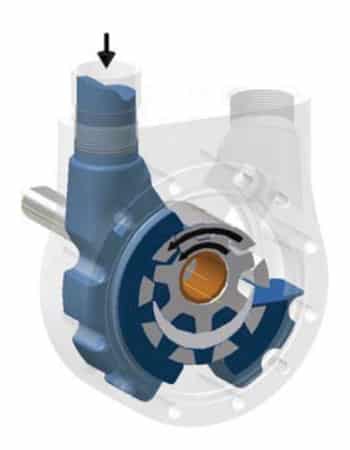
The liquid fills the spaces between the idler and rotor teeth and is carried past the crescent partition through the pressure side of the pump.
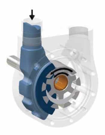
When the teeth mesh on the pressure side, the liquid is forced from the spaces and out through the discharge port.

| Model | NOMINAL FLOW RATE BASED ON 200 SSU @ 100 PSI | |||||||
|---|---|---|---|---|---|---|---|---|
| GPM | LPM | |||||||
| 00LE | 0.9 | @ | 1750 | RPM | 3.4 | @ | 1750 | RPM |
| 0LE | 1.6 | @ | 1750 | RPM | 6.1 | @ | 1750 | RPM |
| 1LE | 2.8 | @ | 1750 | RPM | 10.6 | @ | 1750 | RPM |
| 2LE | 5.0 | @ | 1750 | RPM | 18.9 | @ | 1750 | RPM |
| 5LE | 13.0 | @ | 1750 | RPM | 49.2 | @ | 1750 | RPM |
Note: For speeds above 1800 RPM and/or viscosities above 5000 ssu (1078 cst) consult factory
| Model | NOMINAL FLOW RATE BASED ON 200 SSU @ 50 PSI | |||||||
|---|---|---|---|---|---|---|---|---|
| GPM | LPM | |||||||
| 2C | 8 | @ | 1750 | RPM | 30 | @ | 1750 | RPM |
| 3C | 17 | @ | 1750 | RPM | 64 | @ | 1750 | RPM |
| 4C | 36 | @ | 1750 | RPM | 136 | @ | 1750 | RPM |
| 5C | 61 | @ | 1750 | RPM | 231 | @ | 1750 | RPM |
| 6C | 84 | @ | 1750 | RPM | 318 | @ | 1750 | RPM |
Note: For speeds above 1800 RPM and/or viscosities above 5000 ssu (1078 cst) consult factory
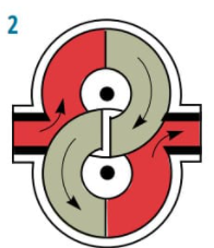
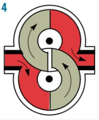
This Tuthill innovation allows positive reversing action without the use of valves. Port positions remain constant regardless of the direction of shaft rotation. It is ideal for use in power transmission applications where the drive shaft direction changes, but the direction of flow must remain constant. Other applications where shaft rotation is unknown, the reversing feature allows the customer to specify the suction and discharge ports.
When shaft rotation changes from counter-clockwise to clockwise, the idler carrier (including the idler gear and crescent) automatically rotates 180º through the suction zone to the position shown in the drawing below. This changes the direction of the flow within the pump without changing port positions. On resumption of counter-clockwise rotation, the crescent will swing back to the original position.

Tuthill Pump Group has been providing positive displacement lubrication pumps for demanding OEM applications since 1927. Since that time, our product portfolio has developed to expand into a variety of markets and applications. Tuthill Pump products successfully handle applications from an extremely low-flow capacity with a high level of accuracy, to applications that are nearly solid in consistency with abrasive characteristics. Know More

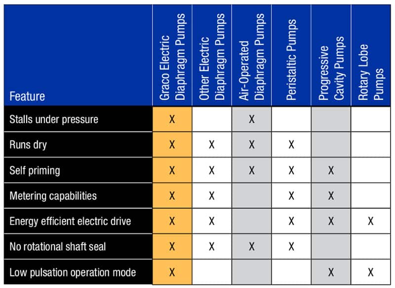
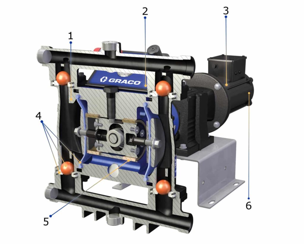
ELIMINATING UNNECESSARY PUMP FAILURES AND IMPROVING YOUR FACILITIES ENERGY EFFICIENCY WITH GRACO’S ELECTRIC DIAPHRAGM PUMPS
Would you like to eliminate unnecessary pump failures for your application? Would you like to improve your facilities energy efficiency and create a quieter and cleaner work environment for your employees? Graco’s Husky e-Series pumps will help you achieve all of those items!
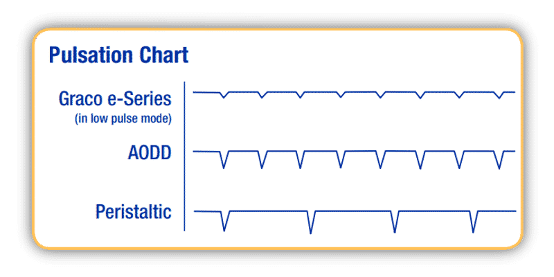
Our Husky e-Series pumps are ideal for applications that require low pulsation and a smooth flow. The air-charged drive allows for the elimination or reduction of pulsation WITHOUT expensive pulsation dampeners or surge tanks.

We’ve listened to what you want out of a pump and designed the Graco e-Series to meet your needs!
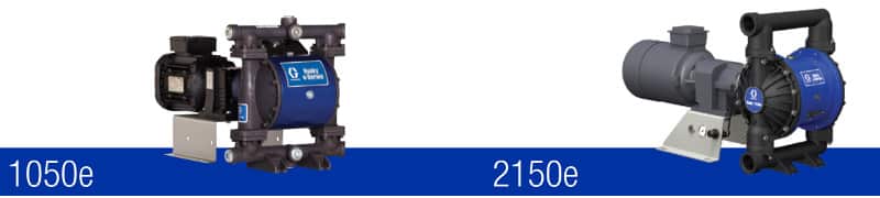
| 1050e | 2150e | ||
|---|---|---|---|
| Maximum fluid working pressure | 70 psi (4.8 bar, 0.48 MPa) | 100 psi (0.69 MPa, 6.9 bar) | |
| Air pressure operating range | 20 – 80 psi (1.4 to 5.5 bar, 0.14 to 0.55 MPa) | 20-100 psi (0.14 to 0.69 MPa, 1.4 to 6.9 bar) | |
| Air inlet size | 3/8 in npt(f) | 3/8 in npt(f) | |
| Maximum suction lift* | Wet: 29 ft (8.8 m); Dry: 16 ft (4.9 m) | Wet or Dry: 18 ft (5.5 m) | |
| Maximum size pumpable solids | 1/8 in (3.2 mm) | 1/4 in (6.3 mm) | |
| Ambient air temperature range for operation and storage** | 32°F to 104°F (0°C to 40°C) | 32°F to 104°F (0°C to 40°C) | |
| Fluid displacement per cycle | 0.15 gallons (0.64 L) | 0.6 gallons (2.27 L) | |
| Maximum free-flow delivery | 42 gpm (158 lpm) | 142 gpm (537 lpm) | |
| Fluid inlet andoutlet size | Metal | 1 in npt(f) or 1 in bspt | 2 in npt (f) or 2 in bspt |
| Plastic | 1 in ANSI/DIN Raised Face Flange | 2 in ANSI/DIN Raised Face Flange | |
| AC motor power | 2 HP | 3, 5, 7.5 HP | |
| BLDC motor power | 2.2 HP | N/A | |
| Operation manual | 334188 | 3A4068 | |
*Reduced if balls don’t seat well due to damaged balls or seats, lightweight balls, or extreme speed of cycling
**Exposure to extreme low temperatures may result in damage to plastic parts
Graco Pumps are a well-known, reliable pump, shrinking maintenance intervals and reducing the nasty surprise of an interruption in production. Graco serves many different industries and applications, providing products for painting, gluing, building, and marine applications amongst many other industrial processing applications.
Know more. All Pumps has these pumps and parts in stock and is ready to help with your requirements today. Contact Us
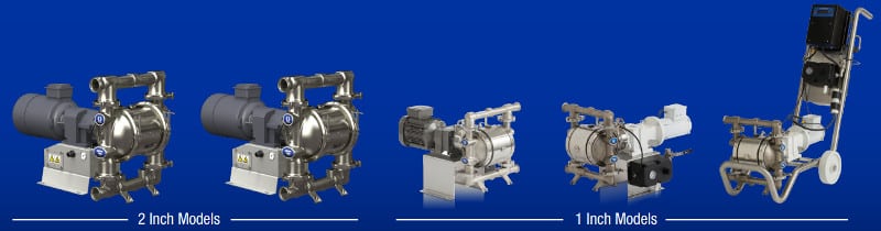
Are you ready to take your food manufacturing process to the next level? Graco’s SaniForce e-series pumps save on energy and extra equipment while hygienically moving fluids over 100 gpm (378 lpm) and 1/4” (6.3 mm) particulates! The low pulsation mode is gentle on shear-sensitive materials to maintain the integrity of your highest-quality ingredients.


We’ve listened to what you want out of a pump and designed the Graco e-Series to meet your needs!

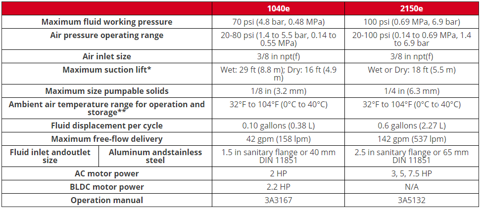
*Reduced if balls don’t seat well due to damaged balls or seats, lightweight balls, or extreme speed of cycling.
**Exposure to extreme low temperatures may result in damage to plastic parts
Graco Pumps are a well-known, reliable pump, shrinking maintenance intervals and reducing the nasty surprise of an interruption in production. Graco serves many different industries and applications, providing products for painting, gluing, building and marine applications amongst many other industrial processing applications. Know more.
All Pumps has these pumps and parts in stock and is ready to help with your requirements today. Contact Us

Beavis & Bartels needed specialised pumps as part of the 50,000m² warehouse and office of the Aldi Retail Chain. They needed to have pumps designed specifically for truck washing and another type of pump specifically for handling rainwater filtration.
To solve the client’s need, the team at All-Pumps provided two types of pumps: packaged rainwater pumps and filtration setups, and some truck wash pumps.

For the truck wash pump, we brought in some Grundfos Pumps. Grundfos manufactures world-class water pumps and pumping systems certified to environmental standard ISO 14001. Know more.

And to handle their rainwater filtration need we brought in some Javelin cold water booster pumps. Javelin was established to provide a package pump solution that is of high quality, reliable, competitive and energy efficient. Know more.
Proudly Australian made – ALDI’s first store opened in 2001. ALDI has played an important role in the Australian community. Each day, their operations improve the livelihoods of local businesses, create employment opportunities, and deliver high-quality products to Australian families at everyday low prices.
ALDI has worked closely with Australian farmers, producers and manufacturers to establish long-term relationships. Know more.